
Thevenin's Theorem
In this article, we explain thevenin's theorem.
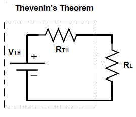
Thevenin's theorem states that any combination of voltage sources and resistors can be replaced with a single voltage source and a single resistor.
Thevenin's theorem, thus, greatly reduces and simplifies a circuit.
In the end, thevenin's theorem produces a single voltage source, a single resistor, and the load. However, the thevenin equivalent does not take into account the resistance of the load (the output the circuit is powering). Therefore, at the end is a circuit that produces the thevenin voltage, thevenin resistance, and a the load resistance.
Therefore, in the end, a voltage divider circuit exists between the thevenin equivalent resistance and the load resistance, and we can calculate how much voltage each gets through the voltage divsion formula.
The great thing about thevenin's theorem is the simplicity it creates. Basically, thevenin's equivalent looks at the entire circuit except the load of the circuit. It then simplifies all the voltage sources into a single voltage source and all resistors into a single equivalent resistor. At the end, we just have the single voltage source, single resistor, and the load (resistance). It forms a very simple voltage division circuit between the single equivalent resistor and the load resistance.
In norton's theorem, the circuit is reduced to a single current source in parallel with a single resistor, along with the load resistance.
So let's now go over an example circuit, so that you can see how thevenin's theorem works.
Example of Thevenin's Theorem
So, below, we have a circuit that we will break down.
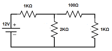
So this circuit is a typical circuit that has a voltage source and several resistors.
In order to produce the equivalent thevenin resistance, we have to simplify all of the resistors into an equivalent resistance, excluding the load (load resistance).
To do this, we find the resistance of the 1KΩ and the 2KΩ resistor. Since they are in parallel, the equivalent resistance is 1KΩ || 2KΩ = (1KΩ)(2KΩ)/(1KΩ + 2KΩ)= 667Ω.
We then add the 100Ω resistor to the 667Ω equivalent resistance. This gives us 767Ω.
So the equivalent thevenin resistance is 767Ω.
This is shown in the circuit below.
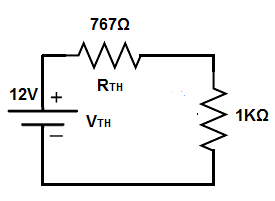
So now you see that we have a voltage source and 2 resistors that are in series.
This forms a voltage divider circuit.
The 12V divides up between the 767Ω and the 1KΩ resistor.
Doing the calculations, this yields 5.2V across the 767Ω resistor, since 12V(767Ω)/(767Ω + 1KΩ)= 5.2V and 6.8V across the 1KΩ resistor, since 12V(1KΩ)/(767Ω + 1KΩ)= 6.8V.
As you can see, a simple voltage divider circuit.
The current through the circuit can be calculated with
ohm's law. The current is, I=V/R= 12V/1,767Ω= 6.8mA.
Thevenin's Theorem with Multiple Power Sources
Just to show also an example, where there are multiple voltage sources, you simply find the equivalent voltage and make it into one voltage source.
We'll analyze the circuit below.
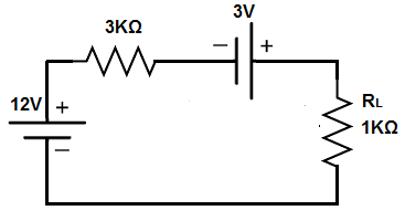
If you simply look at the circuit and use a circuit analysis tool such as KVL, you can see that both voltages add up because their polarities work together.
Therefore, the thevenin voltage is 15V (12V + 3V).
The 3KΩ is already the thevenin resistance.
This produces the following circuit shown below.
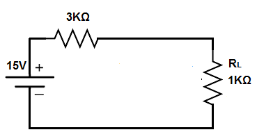
So now you see the voltage divider circuit again.
Doing the calculation gives 9V across the 3KΩ resistor, since since 12V(3KΩ)/(3KΩ + 1KΩ)= 9V and 3V across the 1KΩ resistor, since 12V(1KΩ)/(3KΩ + 1KΩ)= 3V.
The current flowing through this circuit is,
I=V/R= 12V/4KΩ= 3mA.
And this is how thevenin's theorem works. It greatly
simplifies a circuit into a single voltage source and a single resistor. With the load resistance, it forms a very
easy voltage divider circuit, so that analysis is easy.
Related Resources
Kirchhoff's Voltage Law
What is an Ideal Current Source?
What is a Constant Current Source?
RMS Voltage and Current- Explained