How to Build a Voltage Polarity Indicator Circuit
In this circuit, we will show how to build a voltage polarity indicator circuit.
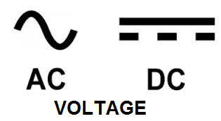
This is a circuit which can detect whether the voltage input into the circuit is DC voltage or AC voltage.
Depending on whether it is AC or DC voltage determines which LEDs light up.
If the voltage is DC, only 1 LED turns on.
If the voltage is AC, both LEDs turn on.
This is because DC voltage only conducts current in one direction. Therefore, current can only flow through one LED.
Remember that an LED is a light-emitting diode. Diodes can only conduct current in one direction, from its anode to its cathode. It can't conduct across from cathode to anode, because the resistance is too high when the diode is reverse biased. Therefore, in DC, it can only turn on LED 1.
AC, however, conducts current in both directions. So both LEDs turn on. This is because AC voltage constantly switches its polarity back and forth, from positive to negative and from negative to positive. In the United States, the AC voltage frequency is 60Hz. This means that every second, the ac voltage switches polarity 60 times. Therefore, since it's so fast, the LEDs appear as if they're always on. Countries throughout the world either use 50Hz or 60Hz as their AC voltage frequency. Both are fast enough to appear as if the LEDs are always on.
So this is how we can tell what voltage is input into the circuit.
Components
- 470Ω resistor
- Red LED
- Green LED
The 470Ω resistor serves as a current-limiting resistor for both LEDs.
You don't have to choose different color LEDs, but we do so, so that it's more easily seen in the circuit.
Voltage Polarity Indicator Circuit
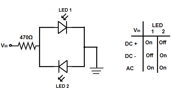
The voltage polarity indicator circuit we will build with zener diodes is shown below.
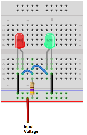
The breadboard schematic of the above circuit is shown below.
So for this circuit, we have a 470Ω resistor in series with the power supply and connected to 2 LEDs in parallel. The first LED is forward biased, meaning that the anode is connected to the positive voltage supply. And the second LED is reverse biased, meaning the cathode is connected to the positive voltage supply. The other sides of the LEDs are connected to ground.
Vin is where the input voltage comes in which is being input into the circuit. This is the signal which this circuit will test to see if it is forward DC, reverse DC, or AC.
The chart above shows all the combinations that can occur.
If the signal is a forward DC signal, meaning it travels from VIN to ground, only LED 1 will turn on. This is because DC goes to only one direction, from Vin to ground. Being that only one LED is forward biased, the DC current can only light LED 1 and travel to ground.
If the signal input is a reverse DC current, meaning it travels from ground to VIN, the other LED, LED 2, will light up in response. This is because the current travels in the opposite direction. Now, in reference to this current, LED 2 is forward biased and LED 1 is reverse biased. Therefore, a reverse DC current can only light LED 2. If you want to test both forward and reverse DC currents, hook up a forward DC current to VIN and then switch the polarities of the leads (making it reverse). You will observe that LED 1 lights up and then when switching the leads, LED 2 will then light up.
If the signal input into the circuit is an AC signal, then both LEDs will light up. This is because AC signals switch polarities constantly. Therefore, both LEDs will be lit.
Again, this circuit is used for determining voltage polarities and whether the voltage input is DC or AC.
And this is how a voltage polarity indicator circuit can be built.
Related Resources
How to Build a Voltage Sensor Circuit