
How to Build a Voltage Sensor Circuit
In this circuit, we will show how to build a voltage sensor circuit.
A voltage sensor circuit is a circuit that can sense the voltage input into it. If the voltage reaches a certain threshold, then an indicator, such as an LED, will turn on.
This is not a voltmeter circuit, where we know or are measuring the amount of voltage input into it. That's a different thing entirely.
This is a voltage sensor circuit, where if we get to a certain level of voltage, then the output will turn on.
And we can build a voltage sensor circuit, simply with a voltage comparator chip or an op amp that can function as a voltage comparator.
A voltage comparator chip is a chip that contains 1 or more op amps. Using a single op amp, we can determine a threshold level for voltage.
A op amp has 2 inputs and 1 output. The 2 inputs are the noninverting input and the inverting input. Into the ninverting input, we place the reference voltage or the threshold voltage. If the voltage at the noninverting terminal reaches or goes above this level, the output will turn on.
Therefore, once we feed a certain level of voltage into the inverting terminal, if the voltage at the noninverting terminal goes above, an output, such as an LED, will light up.
This is how we can know that the voltage is above the threshold point.
And this is how we can build a voltage sensor circuit with an op amp chip functioning as a voltage comparator.
Components
- LM741
- 470Ω resistor
- LED
You can really use any voltage comparator chip that you have.
In this circuit, we will use the general LM741 operational amplifier to act and function as a voltage comparator.
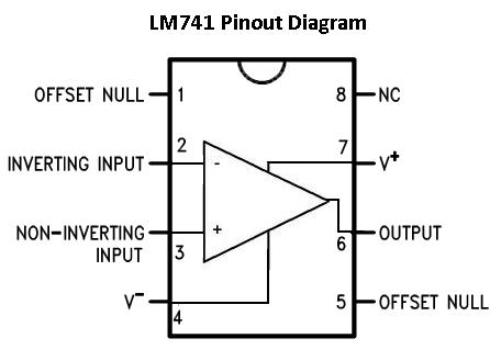
The LM741 is an 8-pin chip.
If you would like to understand all the pin connections of the LM741 op amp, see LM741 Op Amp- Pinout Connections. This article explains all of the 8 pins of the LM741 and what each one does.
The LM741 pinout is shown below.
How this chip functions a voltage comparator and how all voltage comparators work is we feed 2 voltage signals into each of the inputs of the op amp. An op amp has 2 inputs, the + input, or the noinverting input and the - input, or the inverting input.
If the voltage at the noninverting terminal is less than at the noninverting terminal, then the output will be go LOW or at the voltage value of V-.
If the voltage at the noninverting terminal is greater, then the output will be ON or at the voltage value of
VCC.
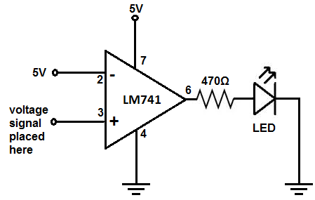
Voltage Sensor Circuit
The voltage sensor circuit that we will build is shown below.
If you want to see this circuit shown from the IC itself, see the following:
Voltage Sensor Circuit shown from the LM741 IC.
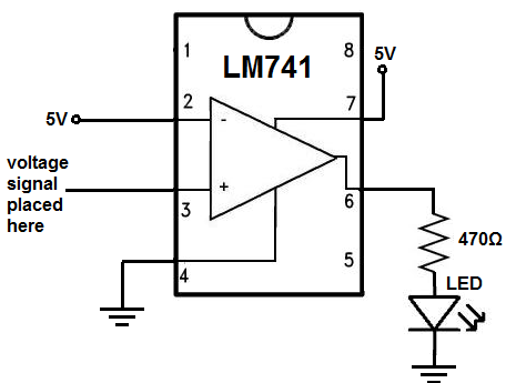
The breadboard schematic of the above circuit is shown below.
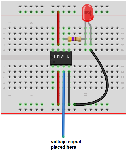
So the LM741 chip is an 8-pin. We only connect 5 out of the 8 pins.
Pin 1 is a NC (Not Connect) and pins 1 and 5 are offset nulls, which we don't connect for this circuit.
Now to power the circuit, we connect V+, pin 7, to 5V and V-, pin 4, to ground. This establishes power to the LM741 chip.
Next, we have the 2 inputs of the op amp of the Lm741.
We connect our reference voltage to the inverting terminal, which is pin 2. This is the voltage that will form the threshold voltage for the circuit.
To the noninverting terminal, we connect the voltage signal we want to test. If the voltage at the noninverting terminal is less than at the threshold voltage at the noninverting terminal, the output will not turn on, because the threshold has not been reached. However, once the voltage at the noninverting terminal goes above the voltage at the inverting terminal, then the output, at pin 5, will turn on.
And, lastly, to the output pin of the LM741, which is pin 5, we connect our output which in this case is an LED along with a 470Ω current-limiting resistor so that the LED doesn't blow out.
This completes all the connections for our circuit.
How the Circuit Works
So, we have our reference voltage of 5V connected to the inverting terminal. This 5V forms our voltage threshold level. If the voltage at the noninverting terminal is less than 5V, then the output will be off or LOW. If the voltage at the noninverting terminal is greater than 5V, the output will be on or HIGH.
To the noninverting terminal, we connect the test voltage signal we want to test.
How the circuit works is very basic. If the voltage at the noninverting terminal is less, the LED is off. If it is greater, the LED turns on.
This is how we form a voltage sensor circuit based on any voltage value.
We can, of course, change the voltage anywhere from -15V to +15V.
If you want to be able to constantly vary the voltage, you can place a potentiometer either at the inverting terminal or noninverting terminal or both and connect it to greater voltage to get a greater varying range.
But this is how a basic voltage sensor can work.
Related Resources
How to Build a Current Sensor Circuit
How to Build a Voltage Polarity Circuit