
When a Circuit Needs Buffering
In this article, we explain when you need to buffer a circuit.
What is meant by buffering a circuit is using a buffer in a circuit.
Using a buffer in a circuit achieves an important effect in the circuit.
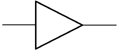
A buffer is basically a high-impedance device that accepts a voltage input and outputs the same voltage as output.
The advantage of a buffer is that it has a high input impedance. Why is a high input impedance advantageous? Because if you go to ohm's law, voltage gets allocated to a circuit in accordance to the resistance or impedance of a device. Voltage= Current x Resistance (V= IR). Therefore, if a device has a high input impedance, it consumes most of the voltage from a given source. If a device has a low impedance, the voltage, for instance from a power source, may not fall across it, since the impedance is so low. This is especially true if there is a resistance in series with this load, making the voltage be divided between the load and the other resistance.
Therefore, to make sure the voltage falls across the device, we use a buffer. Since a buffer has extremely high input impedance, it consumes practically all of the voltage from a voltage divider circuit. And to the output of the buffer, we simply connect the output device. This output device (usually a low impedance) now gets the full voltage.
This is why a buffer is so important.
For devices that have low impedance, it allows us to get the full voltage from a given source and fully power that low impedance device.
Buffering a circuit is common practice for this reason.
Let's go for 2 specific examples of circuits.
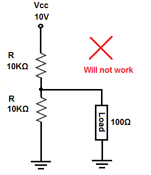
So the above circuit will not work and it will be explained now why not.
So in the circuit above, we have a voltage divider between the 2 10KΩ resistors. Since the resistors are of equal value and the power source is 10V, the voltage at the output where the load is connected to is 5V.
Let's say the load needs about 5V in order to turn on.
If we connect the load to the output of this voltage divider, which produces 5V, the load wouldn't anywhere near 5V. In fact, it would get around 0.5V, which means it wouldn't turn on at all.
Why is this? This is because in this circuit, there are actually 2 voltage dividers. The first, as we stated is between the 2 10KΩ resistors and the second voltage divider is now between the bottom 10KΩ resistor and the 100Ω load. This forms a second voltage divider. If you do the math using ohm's law, the voltage across the 100Ω resistor is, V= VIN(R2/R1 + R2, which is V= 5V (100Ω/10.1KΩ =0.5V). Therefore, it does not receive anything close to the 5V it needs to turn on. The 10KΩ resistor, being much larger, dominates and takes about 4.95V of the 5V.
So, again, the load, needing about 5V will not turn. It receives only 0.5V due to the voltage division.
Now let's fix this circuit using a buffer. We'll now buffer the circuit.
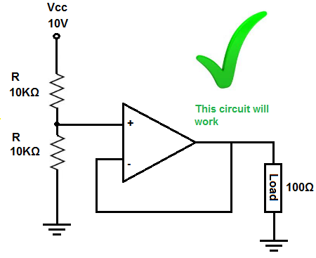
So now we have the same circuit but we've added a buffer.
Now the circuit will work because the buffer, being of extremely high impedance, consumes most of the voltage produced from the voltage divider circuit, which is 5V.
It then passes this 5V to output, which powers on the load, which needs about 5V.
So a buffer normally has several megohms of resistance. For simplicity sake, let's say it offers 100MΩ of resistance. Many offer much more than this. But we'll just use this amount for this example. If you take 100MΩ in series with 10KΩ and the voltage supplying both these resistances is 5V, the 100MΩ (representing the buffer's input impedance) takes 4.999V out of the voltage. So basically all of it.
So this is how a buffer works to power on devices.
Related Resources
How to Build a Buffer Circuit with a 4050 Chip