
How to Build a 4066 Quad Bilateral Switch Circuit
In this circuit, we will show how to connect a bilateral switch chip to inputs and outputs using the 4066 quad bilateral switch chip.
The 4066 really functions as an analog switch. The 4066 is an IC composed of switches which are designed to switch analog signals via digital control. What this means is we feed an analog signal into the input of the switch and it reaches the output only if a HIGH digital signal is fed into the control (or enable) terminal. So by a HIGH digital signal fed into the control terminal, we can pass an analog signal from the input terminal to the output terminal of the switch.
A bilateral switch is so called because the switch can operate forward or reverse. This means that either side of the switch can be used as the input. So current can flow in one direction and the other direction, depending on which side is the input.
A bilateral switch acts as a single pole, single throw switch.
The 4066 is a quad bilateral switch circuit, meaning that is composed of 4 switches.
Each switch has a single input and a single output terminal.
Each switch also has a control or enable terminal. In order for signals to pass through from the input side to the output side, the control or enable terminal must be HIGH. You can view the control terminal as the signal which closes the switch so that the input signal can cross over to the output. Without the control or enable switch, there can be no output. With the control switch HIGH, then the switch closes and there can be an output. So, the control logic is when a LOW signal is feeding the control terminal, the switch is open or OFF. When a HIGH signal is feeding the control terminal, the switch is closed or ON.
In this circuit, we will show the basic functionality of the 4066 chip
by passing analog signals through 2 of the switches by digital control.
Components Needed
- 4066 Quad Bilateral Switch Chip
- 2 Pushbutton
- 2 10KΩ resistors
- Function Generator
The 4066 quad bilateral switch chip is a chip that is made up of 4 switches. It can be obtained cheaply at a number of online electronic retailers. One place it can be obtained is at Taydaelectronics at the following link: TaydaElectronics- 4066 Quad Bilateral Switch IC.
The 4066 is a 14-pin chip.
The datasheet for the 4066 can be found at the following link: 4066 Quad Bilateral Switch Datasheet.
The 4066 has a wide operating voltage of 5V-15V.
The pinout of the 4066 chip is shown below.
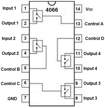
As the quad term implies, the 4066 is composed up of 4 switches. The switches are labeled from 1 to 4.
Each switch has an input, output, and control terminal. The control terminal enables the input to go to output.
VDD and ground, pins 14 and 7, are the power pins.
4066 Quad Bilateral Switch Circuit
The quad bilateral switch circuit we will build with a 4066 chip is
shown below.
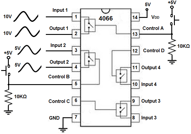
First, to power the 4066, we connect 5V of power to VDD, pin 14, and we connect the ground pin, pin 7, to ground. This establishes sufficient power to the chip.
For this circuit, we are only going to be using 2 of the 4 switches. Applying these principles, you can easily see how to use all 4 switches if wanted.
To the inputs of the 2 switches, we feed an analog signal. The most common waveform is a sine wave.
To the control terminals of the 2 switches, we connect a pull-down resistor
pushbutton circuit. When unpressed, the pushbutton has the signal LOW by default. When
pressed down, the pushbutton makes the signal HIGH.
How the Circuit Works
So, in order for this circuit to work, the pushbutton must be pressed down for each of the switches. This enables the signal at the input to go to the output.
If the pushbuttons are not pressed down, then no signal will appear at the outputs.
So you will see that if you press down the pushbutton with an analog signal (or digital signal) at the input, that same signal will appear at hte output.
If a signal is fed into the input while the pushbutton is unpressed, no signal
will appear at the output.
Related Resources
How to Vary the Brightness of an LED
How to Build an LED Driver Circuit
How to Build an LED Flasher Circuit