
How to Connect a Voltage Regulator in a Circuit
In this article, we go over how to connect a voltage regulator to a circuit to get a specific DC output regulated voltage.
Depending on the voltage regulator in use, we can get a regulated positive or negative voltage, at whichever voltage we want. The LM78XX voltage regulators are a popular kind for regulating and outputting positive voltage, while the LM79XX are a popular series of regulators for negative voltage. In this article, we use a positive voltage regulator, which outputs 5V, the LM7805 regulator.
Before we can hook up the circuit, let's first go over the pinout diagram of the voltage regulator, which is vital for hooking up the circuit.
A voltage regulator is a 3-terminal device.
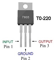
Pin 1 is the Input Pin. The output voltage of whatever voltage source you want to regulate down (whether it's a transformer, battery, etc.) is fed into this pin. So for instance, if you have 10 volts coming from a transformer that you want regulated down to 5 volts, the output of the transformer (the 10 volts) is fed into the regulator input (pin 1) so that the regulator can regulate it down to your wanted voltage (5 volts). The voltage regulator should always be fed as smooth of a DC signal as possible (which gives the best regulated output) so it can regulate it down to its specified voltage. Remember, the input voltage has to be larger than the voltage that the regulator regulates out. In this case, we are using a LM7805, which outputs 5 volts. In order for the regulator to output 5 volts, the voltage entering has to be at least 2 volts higher, so it has to be at least 7 volts. 7 volts would work perfect. However, for experimental purposes and ease of getting parts, we will use a 9-volt battery as our input voltage.
Pin 2 is Ground. It hooks up to the ground in our circuit. Without ground, the circuit couldn't be complete because the voltage wouldn't have electric potential and the circuit wouldn't have a return path. Ground is essential.
Pin 3 is the Output Pin. This is the pin that gives out the regulated voltage, which, in this case, is 5 volts. At the end of this experiment, when our circuit is hooked up, we're going to read out the voltage with a multimeter and it should give out close to 5 volts.
Okay, now let's build the circuit.
Components Needed
- LM7805 Voltage Regulator Chip
- 9-volt Battery
- 0.33uF Ceramic Capacitor
- 0.1uF Ceramic Capacitor
- 1KΩ Resistor
- LED
If you don't have all the parts, just follow along. You can buy them at anytime and come back to this page and do the experiment.
Let's view the complete circuit now and explanations will ensue.
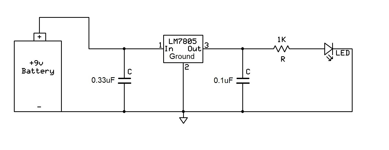
The first capacitor, the 0.33uF ceramic capacitor, is hooked up after the voltage source, in this case the 9-volt battery, and before the input of the LM7805 regulator. This capacitor is there to filter out any noise coming from the voltage source (the battery). The voltage regulator works best and will be most efficient when a clean DC signal is fed into it. We don't want any ac noise (ripple) imposed on the DC line voltage. The capacitor, in essence, acts as a bypass capacitor. It shorts the AC signal of the voltage signal (which is noise on the voltage signal) to ground and only the DC portion of the signal goes into the regulator.
The second capacitor, the 0.1uF ceramic capacitor, is hooked up after the voltage regulator. This capacitor is there again to filter out any noise or high-frequency (ac) signals that may be on the DC voltage line. For a circuit like this, where we're lighting an LED, it isn't exactly crucial to have a pure DC signal, but in other applications, such as when outputting voltage to power a logic chip, which needs a precise voltage fed into it in order to give the correct logic output, it is crucial. That's why it's a good idea to get into hooking up a voltage regulator properly from the start.
Okay, so let's recap on the circuit. The circuit begins at the 9-volt battery. This produces a voltage of 9 volts. The first capacitor, the ceramic 0.33uF, cleans up the signal if any (ac) noise is present on this. It shorts this noise to ground and allows the pure DC signal into the regulator. The regulator regulates this voltage down to 5 volts. After it comes out of the regulator, the other capacitor, the 0.1uF ceramic, cleans up any high-frequency or ac noise that may come out, again to produce a clean DC signal. Now this DC voltage, clean and crisp, is ready to power whatever you want it to, in this case, the load is a resistor and a LED.
Keep in mind that the design of a voltage regulator depends on the voltage regulator being used and the intended
use of a circuit. Always consult the
Manufacturer's Datasheet for the voltage regulator in use for a circuit to see how to hook it up with
the necessary required external components. Usually the only external components necessary are just capacitors, though
heat sinks may also need to be added when heat dissipation is necessary. The Datasheet specifies which value of
capacitors to use, so it's a good idea to learn from the people who manufacturered the chip. Also, the circuit may change
based on its intended use. When the load of a circuit is stable and unchanging, as in the
example above, it is usually
not necessary to add a large electrolytic capacitor on the output to act as a smoothing capacitor. But if you're going
to have
a varying load, a potentiometer, for instance, on the output, it is well advised to add an electrolytic capacitor in
parallel
to the ceramic capacitor. This electrolytic capacitor acts as a smoothing capacitor, when load resistance changes
cause abrupt voltage spikes and drops, in a circuit. This capacitor charges up with voltage when the circuit has excess
spikes in current and discharges to supply voltage when the circuit is low on current. Therefore, it has a smoothing
effect and even things out. Essentially, it acts as a load balancer. More will be on this for more advanced projects,
but this page is a good start for those starting off in connecting voltage regulators for basic circuits.
Related Resources
How to Test a Voltage Regulator
What is an Adjustable Voltage Regulator?
How to Connect an Adjustable Voltage Regulator
How to Build a Zener Diode Voltage Regulator