
How to Build a 10 Segment LED Bar Graph Circuit with an Arduino
In this project, we are going to show how to connect a 10 segment LED bar graph to an arduino microcontroller and how to control the LED bar graph with the arduino.
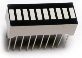
A 10 segment LED bar graph is basically 10 individual LEDs in a package that looks and can function like a bar graph.
Basically, it can simulate bar graph results. For example, if we're measuring battery power in a circuit, the LED bar graph can project the strength of the battery life. If all 10 LEDs are lit, this could mean full strength. If 5 LEDs are lit, this could mean it's at half strength. If 1 or no LEDs are lit, it can mean the battery is dead. So uses such as this are many times what LED bar graphs are used for.
In this circuit, we're going to use the LED bar graph to show the level of voltage that a potentiometer has.
When the potentiometer is turned all the way to one side so that its resistance is 0Ω, its voltage will be essentially 0V. In this case, the LED bar graph will have no LEDs lit. As we turn the potentiometer so that its resistance, and, therefore, voltage increases, the number of LEDs that light up on the bar graph increase proportionally. We do and show the math below so that there's a exact relationship between the voltage and the LEDs lit on the bar graph.
With this circuit, you can develop a number of VU (volume unit) or SVI (standard volume indicator) devices.
This circuit can be modified to create almost any type of measuring device. You can replace the potentiometer
so with any type of sensor measurement to measure anything. For example, if we replace the potentiometer with a
resistor and photoresistor in series, we can build a light-sensing device and then the LED bar graph and light to show
the light intensity that the photoresistor is detecting. We can put in a force-sensing resistor that measures the amount of
force applied to the sensor and then the value proportionately on the LED bar graph. This circuit can be a building block
to build a number of other circuits.
Components Needed
- 10 Segment LED Bar Graph
- 10 220Ω resistor
- Arduino
The 10 segment LED bar graph can be obtained for about $1 or a little over.
The 10 segment LED bar graph is a 20 pin chip. Each LED has 2 terminals, the anode and the cathode. The anode of each LED connects to positive voltage. This voltage will be supplied when the digital pin is brought HIGH On the arduino board. And the cathode of each LED connects to ground.
The pinout for the 10 segment LED bar graph is shown below.
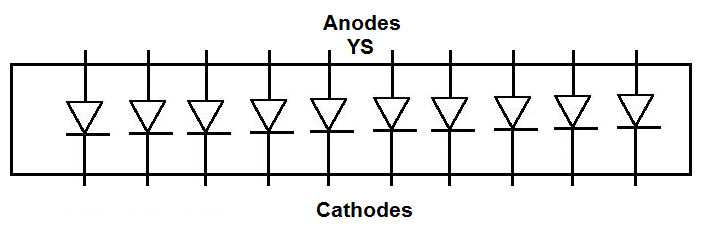
How you can differentiate between the anode side and the cathode side is the anode side is marked with the letters, YS. This is the side you will connect positive voltage to.
Current-limiting resistors, as with all LEDs, must be used with the 10 segment LED bar graph. If they aren't, there is a very high chance you are going to blow out 1 or some of the LEDs, which will destroy the whole LED bar graph, requiring you to have to replace it. Therefore, always use current-limiting resistors. 220Ω resistors work perfectly fine.
We will connect each of the anodes of the LEDs to one of the digital pins on the arduino board. When
in a LOW state, the LED will be off. When in a HIGH state, the LED will be on.
10-Segment LED Bar Graph Circuit with an Arduino
The 10-segment LED bar graph circuit we will build to be controlled with manual pushbuttons is shown below.
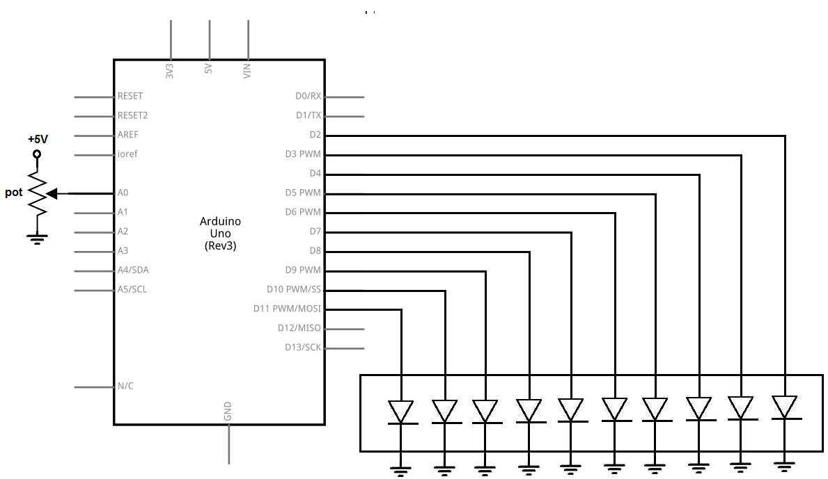
In this circuit, we connect all of the cathodes of the LED to ground.
We then connect each of the anodes of the LED bar graph to a digital pin on the arduino. We connect the first of the pin of the LED bar graph to digital pin 11 on the arduino. We connect the second pin to D10, the third pin to D9, the fourth pin to D8, the fifth pin to D7, the sixth pin to D6, the seventh pin to D5, the eight pin to D4, the ninth pin to D3, and the tenth pin to D2.
We use 220Ω resistors for each of the LEDs to limit current to the LEDs, so that an LED doesn't blow out.
In our code, when we draw an LED HIGH, we turn on the LED. When the LED is LOW, it is off.
Code
The code so that the LED bar graph lights up in porportion to the resistance or voltage that the potentiometer is outputting is shown below.
const int LED1= 11;
const int LED2= 10;
const int LED3= 9;
const int LED4= 8;
const int LED5= 7;
const int LED6= 6;
const int LED7= 5;
const int LED8= 4;
const int LED9= 3;
const int LED10= 2;
const int potentiometer= A0;
int value=0;
void setup()
{
pinMode(LED1, OUTPUT);
pinMode(LED2, OUTPUT);
pinMode(LED3, OUTPUT);
pinMode(LED4, OUTPUT);
pinMode (LED5, OUTPUT);
pinMode (LED6, OUTPUT);
pinMode (LED7, OUTPUT);
pinMode (LED8, OUTPUT);
pinMode (LED9, OUTPUT);
pinMode (LED10, OUTPUT);
pinMode (potentiometer, INPUT);
Serial.begin(9600);
}
void loop()
{
value= analogRead(potentiometer);
Serial.println(value);
if (value == 0)
{
digitalWrite (LED1, LOW);
digitalWrite (LED2, LOW);
digitalWrite (LED3, LOW);
digitalWrite (LED4, LOW);
digitalWrite (LED5, LOW);
digitalWrite (LED6, LOW);
digitalWrite (LED7, LOW);
digitalWrite (LED8, LOW);
digitalWrite (LED9, LOW);
digitalWrite (LED10, LOW);
}
if ((value >0) && (value < 103))
{
digitalWrite (LED1, HIGH);
digitalWrite (LED2, LOW);
digitalWrite (LED3, LOW);
digitalWrite (LED4, LOW);
digitalWrite (LED5, LOW);
digitalWrite (LED6, LOW);
digitalWrite (LED7, LOW);
digitalWrite (LED8, LOW);
digitalWrite (LED9, LOW);
digitalWrite (LED10, LOW);
}
if ((value >= 103) && (value < 205))
{
digitalWrite (LED1, HIGH);
digitalWrite (LED2, HIGH);
digitalWrite (LED3, LOW);
digitalWrite (LED4, LOW);
digitalWrite (LED5, LOW);
digitalWrite (LED6, LOW);
digitalWrite (LED7, LOW);
digitalWrite (LED8, LOW);
digitalWrite (LED9, LOW);
digitalWrite (LED10, LOW);
}
if ((value >= 206) && (value < 308))
{
digitalWrite (LED1, HIGH);
digitalWrite (LED2, HIGH);
digitalWrite (LED3, HIGH);
digitalWrite (LED4, LOW);
digitalWrite (LED5, LOW);
digitalWrite (LED6, LOW);
digitalWrite (LED7, LOW);
digitalWrite (LED8, LOW);
digitalWrite (LED9, LOW);
digitalWrite (LED10, LOW);
}
if ((value >= 309) && (value < 410))
{
digitalWrite (LED1, HIGH);
digitalWrite (LED2, HIGH);
digitalWrite (LED3, HIGH);
digitalWrite (LED4, HIGH);
digitalWrite (LED5, LOW);
digitalWrite (LED6, LOW);
digitalWrite (LED7, LOW);
digitalWrite (LED8, LOW);
digitalWrite (LED9, LOW);
digitalWrite (LED10, LOW);
}
if ((value >= 411) && (value < 512))
{
digitalWrite (LED1, HIGH);
digitalWrite (LED2, HIGH);
digitalWrite (LED3, HIGH);
digitalWrite (LED4, HIGH);
digitalWrite (LED5, HIGH);
digitalWrite (LED6, LOW);
digitalWrite (LED7, LOW);
digitalWrite (LED8, LOW);
digitalWrite (LED9, LOW);
digitalWrite (LED10, LOW);
}
if ((value >= 513) && (value < 615))
{
digitalWrite (LED1, HIGH);
digitalWrite (LED2, HIGH);
digitalWrite (LED3, HIGH);
digitalWrite (LED4, HIGH);
digitalWrite (LED5, HIGH);
digitalWrite (LED6, HIGH);
digitalWrite (LED7, LOW);
digitalWrite (LED8, LOW);
digitalWrite (LED9, LOW);
digitalWrite (LED10, LOW);
}
if ((value >= 616) && (value < 717))
{
digitalWrite (LED1, HIGH);
digitalWrite (LED2, HIGH);
digitalWrite (LED3, HIGH);
digitalWrite (LED4, HIGH);
digitalWrite (LED5, HIGH);
digitalWrite (LED6, HIGH);
digitalWrite (LED7, HIGH);
digitalWrite (LED8, LOW);
digitalWrite (LED9, LOW);
digitalWrite (LED10, LOW);
}
if ((value >= 718) && (value < 819))
{
digitalWrite (LED1, HIGH);
digitalWrite (LED2, HIGH);
digitalWrite (LED3, HIGH);
digitalWrite (LED4, HIGH);
digitalWrite (LED5, HIGH);
digitalWrite (LED6, HIGH);
digitalWrite (LED7, HIGH);
digitalWrite (LED8, HIGH);
digitalWrite (LED9, LOW);
digitalWrite (LED10, LOW);
}
if ((value >= 820) && (value < 921))
{
digitalWrite (LED1, HIGH);
digitalWrite (LED2, HIGH);
digitalWrite (LED3, HIGH);
digitalWrite (LED4, HIGH);
digitalWrite (LED5, HIGH);
digitalWrite (LED6, HIGH);
digitalWrite (LED7, HIGH);
digitalWrite (LED8, HIGH);
digitalWrite (LED9, HIGH);
digitalWrite (LED10, LOW);
}
if ((value >= 922) && (value < 1023))
{
digitalWrite (LED1, HIGH);
digitalWrite (LED2, HIGH);
digitalWrite (LED3, HIGH);
digitalWrite (LED4, HIGH);
digitalWrite (LED5, HIGH);
digitalWrite (LED6, HIGH);
digitalWrite (LED7, HIGH);
digitalWrite (LED8, HIGH);
digitalWrite (LED9, HIGH);
digitalWrite (LED10, HIGH);
}
}
So, in our first block of code, we define all the physical pin connections between the LED bar graph and the arduino board. We also declare an integer named value. This value will hold the analog value obtained from the potentiometer at analog pin 0. This value can range anywhere from 0 to 1023.
Next, in the setup() function, we declare all the LEDs as outputs and the potentiometer as an input. We also create a serial monitor in case you want to see what the actual value the potentiometer is outputting.
After this, we have the loop() function. In this function, we read the value from the potentiometer and place this value in the integer value we declared at the beginning of the program. Based on this value, we determine the number of LEDs on the LED bar graph which will light up.
Since there are 10 LEDs in total and the analog value can vary from 0 to 1023, this means that we increase the LEDs that are on by 1 for every 102.3 analog value inrease. This is because 1023/10=102.3. Since 102.3 is a decimal, sometimes, we increase by 103.
So, when the analog value is 0, all the LEDs are off.
When the value is between 1 and 102, 1 LED lights up.
When the value is between 103 and 205, 2 LEDs light up.
When the value is between 206 and 308, 3 LEDs light up.
When the value is between 309 and 410, 4 LEDs light up.
When the value is between 411 and 512, 5 LED lights up.
When the value is between 513 and 615, 6 LEDs light up.
When the value is between 616 and 717, 7 LED lights up.
When the value is between 718 and 819, 8 LEDs light up.
When the value is between 820 and 921, 9 LED lights up.
When the value is between 922 and 1023, 10 LEDs light up.
So when the potentiometer is turned all the way to 0Ω, all LEDS are off. As we turn the potentiometer, increasing its resistance and voltage, the LEDs light up in proportion to this resistance and voltage.
And this is how a VU meter circuit works with an LED bar graph.
Related Resources
How to Build a 10 Segment LED Bar Graph Circuit with Manual Pushbutton Control
How to Build an LM3914 Dot/Bar Display Driver Circuit