
How to Build a 10 Segment LED Bar Graph Circuit
In this project, we are going to show how to connect a 10 segment LED bar graph.
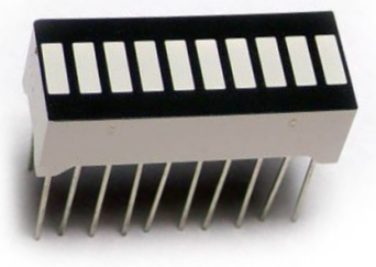
A 10 segment LED bar graph is basically 10 individual LEDs in a package that looks and can function like a bar graph.
Basically, it can simulate bar graph results. For example, if we're measuring battery power in a circuit, the LED bar graph can project the strength. If all 10 LEDs are lit, this could mean full strength. If 5 LEDs are lit, this could mean it's at half strength. If 1 or no LEDs are lit, it can mean the battery is dead. So uses such as this are many times what LED bar graphs are used for.
In this circuit, we're not going to use the LED bar graph to show the result of the strength of a signal of some device. We're simply going to show how to connect the LED bar graph, which is rather simple.
Once you know the pinout, then you can then elaborate on it to build more advanced circuits.
Components Needed
- 10 Segment LED Bar Graph
- 10 220Ω resistor
- 10 Pushbuttons
The 10 segment LED bar graph can be obtained for about $1 or a little over.
The 10 segment LED bar graph is a 20 pin chip. Each LED has 2 terminals, the anode and the cathode. The anode of each LED connects to positive voltage. About 3V will power on the LED. And the cathode of each LED connects to ground.
The pinout for the 10 segment LED bar graph is shown below.
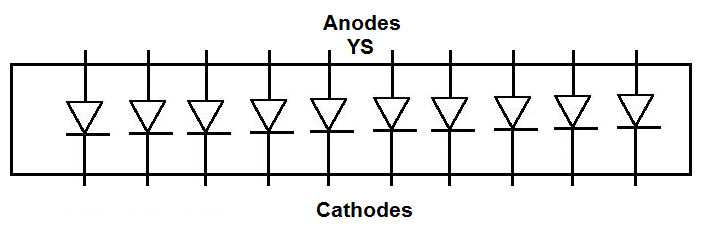
How you can differentiate between the anode side and the cathode side is the anode side is marked with the letters, YS. This is the side you will connect positive voltage to.
Current-limiting resistors, as with all LEDs, must be used with the 10 segment LED bar graph. If they aren't, there is a very high chance you are going to blow out 1 or some of the LEDs, which will destroy the whole LED bar graph, requiring you to have to replace it. Therefore, always use current-limiting resistors. 220Ω resistors work perfectly fine.
We will connect pushbuttons to each of the 10 LEDs. When we push down on a pushbutton, the corresponding LED will light up.
A 10-segment LED is simply 10 individual LEDs.
10-Segment LED Bar Graph Circuit with Manual Pushbutton Control
The 10-segment LED bar graph circuit we will build to be controlled with manual pushbuttons is shown below.
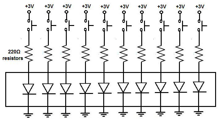
In this circuit, we connect all of the cathodes of the LED to ground.
We then connect each of the anodes of the LED bar graph to positive voltage via a pushbutton. We use 220Ω resistors for each of the LEDs to limit current to the LEDs, so that an LED doesn't blow out.
The resistors function to limit current but also as pull-down resistors. Pull-down resistors are resistors that are normally in a LOW state (grounded) but when the pushbutton is pressed becomes a HIGH state (connectedt to positive voltage).
When the pushbuttons are unpressed, the LEDs are off. They are connected to ground, without any connection to the positive voltage.
When the pushbuttons are pressed down, the LEDs turn on. They are now connected to the positive voltage source and the circuit is now complete. Current flows from the positive voltage source down to ground to light on the LED.
Each of the 10 pushbuttons correspond to the 10 LEDs. If you press down on one pushbutton, that LED will light up. If you press down on multiple pushbuttons, those corresponding LEDs will light up.
Again, this circuit just demonstrates how 10-segment LED bar graphs work. This is not the way you would use an LED bar graph. This circuit does not demonstrate the practical use for an LED bar graph, but just shows how it is connected and how it works.
We will show in future circuits actual practical and real-world uses of the LED bar graph.
Related Resources
How to Build a 10 Segment LED Bar Graph Circuit with an Arduino
How to Build an LM3914 Dot/Bar Display Driver Circuit