
How to Build an LM3914 Dot/Bar Display Driver Circuit
In this project, we are going to show how to connect a LM3914 dot/bar display driver so that it can control 10 LED outputs. With this LM3914 chip, we can control an LED bar graph in either bar mode or dot mode.
Bar mode is a mode in which if full voltage is going to the chip, all 10 LEDs will be lit up.
Dot mode is a mode in which if full voltage is going to the chip, only the tenth LED will be on, not all 10 LEDs. Dot mode only lights up a single LED at a time. If 8/10 of voltage is going to the chip in bar mode, only the eighth LED will be on. Meanwhile, in bar mode, all eight LEDs will be on.
An LED bar graph is a device that can be a visual indicator of voltage output.
LED bar graphs are used often in VU meter circuits, in which the LED bar graph can be lit up in proportion to the amount of voltage a device is outputting.
The LM3914 works well with LED bar graphs because it allows us to adjust the voltage and current going to each LED output by simply
A 10 segment LED bar graph is basically 10 individual LEDs in a package that looks and can function like a bar graph.
Basically, it can simulate bar graph results. For example, if we're measuring battery power in a circuit, the LED bar graph can project the strength of the battery life. If all 10 LEDs are lit, this could mean full strength. If 5 LEDs are lit, this could mean it's at half strength. If 1 or no LEDs are lit, it can mean the battery is dead. So uses such as this are many times what LED bar graphs are used for.
In this circuit, we're going to use the LED bar graph to show the level of voltage that a potentiometer has.
When the potentiometer is turned all the way to one side so that its resistance is 0Ω, its voltage will be essentially 0V. In this case, the LED bar graph will have no LEDs lit. As we turn the potentiometer so that its resistance, and, therefore, voltage increases, the number of LEDs that light up on the bar graph increase proportionally. We do and show the math below so that there's a exact relationship between the voltage and the LEDs lit on the bar graph.
With this circuit, you can develop a number of VU (volume unit) or SVI (standard volume indicator) devices.
This circuit can be modified to create almost any type of measuring device. You can replace the potentiometer
so with any type of sensor measurement to measure anything. For example, if we replace the potentiometer with a
resistor and photoresistor in series, we can build a light-sensing device and then the LED bar graph and light to show
the light intensity that the photoresistor is detecting. We can put in a force-sensing resistor that measures the amount of
force applied to the sensor and then the value proportionately on the LED bar graph. This circuit can be a building block
to build a number of other circuits.
Components Needed
- LM3914 Dot/Bar Display Driver
- 10 Segment LED Bar Graph
- 1.25KΩ resistor
- 3.75KΩ resistor
- Toggle switch
- Potentiometer
The LM3914 can be obtained for about $1 on ebay.
The LM3914 is an 18-pin chip.
The pinout of the LM3914 is shown below.
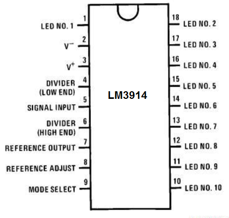
To give power to the LM3914, we connect +5V of power to the pin 3, which is the V+ pin. And then we connect pin 2, V-, to ground. This establishes power to the chip.
Pin 4 is the RLO. According to the datasheet, if you are not using LEDs with leads that are 6" or longer, you can connect this pin directly to ground. If you are using LEDs with pins 6" or longer, then you would place a capacitor in parallel to this pin. Since we are using LEDs with such long leads, we simply connect pin 4 to ground.
Pin 5 is a very important pin. This is the signal pin. This changes the number of LEDs lit on the LED bar graph. To pin 5, we will connect the wiper terminal of a potentiometer. This varies the voltage that is fed into the LM3914. With varying voltage, we get varying LEDs lit. If the voltage is 0V, which means the potentiometer is turned all the way to 0Ω, none of the LEDs will be lit. As we turn the potentiometer, increasing its resistance, more and more LEDs will be turned on until a full 5V is fed into pin 5, in which all the LEDs will be on. Because we are dealing with the range of 0-5V and there are 10 LEDs, an additional LED will turn on for each 0.5V we go up (5V/10= 0.5V). Or for every 0.5V we decrease, an additional LED will turn off (in reverse).
Pins 6, 7, 8 all work together. Resistors R1 and R2 control the biasing of the circuit as far as the current that will flow through the LEDS of the LED bar graph. How these resistors are determined are given by the formulas given by the manufacturer.
The formula to calculate the current through the LEDs is, ILED= 12.5/R1.
How we go about computing this is this: we decide the value of the current we want passing through the LEDs. And then we can calculate resistor R1. According to the datasheet, a good current to flow through the LEDs is 10mA. Therefore we take 10mA to plug it in for ILED. Using 10mA, resistor R1 calculates out to be 1.25KΩ.
The other formula is to calculate the second resistor value R2.
The formula is Ref VOUT= 1.25 (1 + R2/R1).
Our VOUT voltage is 5V. So we plug 5V into this formula. Using the resistor R1 value we calculated before of 1.25KΩ, resistor R2 calculates out to be 3.75KΩ. So these are the 2 values we use for biasing purposes to produce 10mA of current flow through each of the LEDs of the LED bar graph.
Pin is the mode pin. This is the pin that allows us to have the LM3914 in bar mode or in dot mode. When this pin is connected to V+, then the chip is in bar mode. If the pin is connected either to ground or is left unconnected (floating), then the chip is in dot mode.
Pins 1 and 10-18 are the output pins. These are the pins where the LED bar graph connects to. The cathodes of the LEDs of the LED bar graph connect to these pins. Then the anodes of the LEDs connect to +5V. The same voltage that powers the chip can be used for VLED We do not have to connect current-limiting resistors to the LEDs because the R1 resistor functions as the current-limiting resistor.
The 10-segment LED bar graph we will use can be gotten for a little over $1. If you want to see more in-depth detail about it, see How to Build a 10 Segment LED Bar Graph Circuit. This includes the pinout and all the details of how to connect the LED Bar graph.
The potentiometer we will use can really be of any value. So you can use whatever
you have.
10-Segment LED Bar Graph Circuit with an Arduino
The LM3914 bar/dot display driver that we will build to control an LED bar graph is shown below.
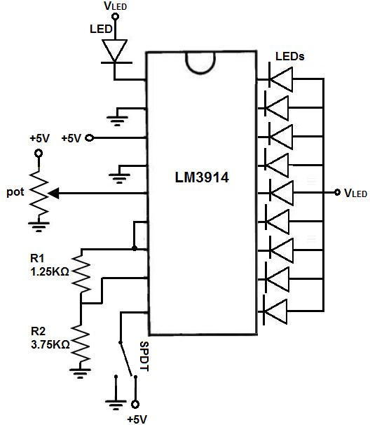
To connect power to the LM3914, we connect +5V to pin 3 and we connect pin 2 to ground. We can use this same voltage for VLED to power on the LEDs. You have the choice: you can use the same power supply to power the chip and the LEDs or separate power supplies. In this circuit, we will be using the same for both.
We ground pin 4 wihtout a capacitor because the leads of the LEDs we use are less than 6".
Next, we connect the potentiometer. We connect one end terminal to 5V and the other end terminal to ground, while connecting the wiper terminal to pin 5. By varying the potentiometer, we change the voltage fed into the pin and this changes the LEDs that are turned on in the LED bar graph. The less voltage, the less LEDs on. As we increase voltage, more LEDs turn on.
Next in pins 6,7, 8, we place our biasing resistors R1 and R2 to obtain the current of 10mA. R1 is 1.25KΩ and 3.75KΩ. The formulas and math of how this was calculated was shown above.
Pin 9 is the mode pin. This can allow us to switch betweeen bar mode and dot mode. We place a toggle switch on this pin so that we can switch between the 2. We connect one side to +5V and the other to ground. If the switch is on +5V, the chip is in bar mode. If the switch is flipped to ground, the chip is in dot mode.
Pins 1 and 10-18 are the output pins. Here we connect the cathodes of the LEDs of the LED bar graph.
We then connect the anodes of the LEDs to +5V. Again no current-limiting resistors are necessary because the resistor R1 acts as the current-limiting resistor.
How the Circuit Works
The potentiometer is the mainstay of the circuit. Depending on the its resistance affects the voltage directly. Remember voltage= current * resistance. If the resistance is 0Ω, the voltage is 0V. In this case, all the LEDs will be off. As the resistance increases, the voltage increases, so the LEDs begin turning on. Since the reference voltage is 5V and there are 10 LEDs, each 0.5V increase turns on an LED.
So at 0.5V, 1 LED turns on.
At 1V, 2 LEDs turn on.
At 1.5V, 3 LEDs turn on.
At 2V, 4 LEDs turn on.
At 2.5V, 5 LEDs turn on.
At 3V, 6 LEDs turn on.
At 3.5V, 7 LEDs turn on.
At 4V, 8 LEDs turn on.
At 4.5V, 9 LEDs turn on.
At 5V, all 10 LEDs turn on.
This is more or less. It may vary by a few tenths of a volt depending on the tolerane of the resistors and if you used the same exact resistances offered. It's not a big deal.
And you can switch easily between bar and graph mode by switching the toggle switch.
And this is how a LM3914 can control an LED bar graph.
Related Resources
How to Build a 10 Segment LED Bar Graph Circuit with Manual Pushbutton Control
How to Build a 10 Segment LED Bar Graph Circuit with an Arduino