
How to Build an H-bridge Circuit to Control 4 Motors
An H-bridge chip such as the L293/SN754410 can control up to 2 motors.
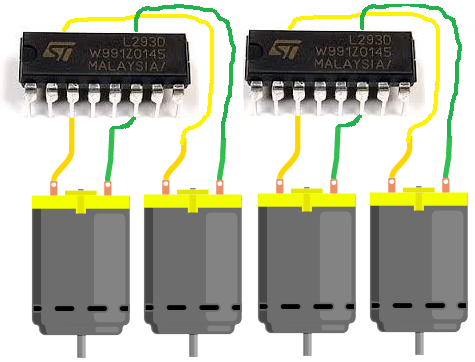
So in order to control 4 motors, we will need to use 2 H-bridge chips and tie them together.
We will build a circuit where all the motors are synchronized, meaning they act in symphony. Thus, if we input so that forward motion is activated, all the motors will spin in a forward direction. If we input reverse mode, all the motors will spin in reverse direction. So the motors act in concert.
This type of circuit is useful for any circuit that needs multiple motors. A common electronic device that now uses 4 DC motors are flying drones. If you go into amazon or any various online retailers to get a toy drone, the majority of them use 4 motors, the 4 of which act in concert. So this type of circuit has very valuable use in the real world.
In actuality, you could use how many motors you want. Since each H-bridge chip can operate 2 motors, then if you wanted to have 8 motors running, then you would need 4 H-bridge chips. If you want 16 motors running, then we need 8 H-bridge chips. You would just have to know how to connect them together, which is relatively simple. It's like just cascading them in a sequence.
But in this circuit, we do 4 motors.
The motor operation is
Components
- 2 L293/SN754410 H-bridge Chips
- 4 DC Motors
- 2 Pushbutton Switches
- 1 Toggle Switch
- 2 10KΩ resistors
- Power Source
The L293/SN754410 H-bridge chip is 16-pin chip that can be used to drive and control inductive loads such as relays, solenoids, DC motors, and bipolar stepper motors.
In this circuit, we will be using it to control 2 DC motors.
The L293/SN754410 is a relatively inexpensive chip that can be obtained for a little over $1. One place that sells the L293 is Tayda Electronics- L293 Driver IC.
Before we build this circuit, you must understand the chip and all of its pin connections. You must always know pin connections when hooking up any chip.
Overall, the L293/SN754410 chips aren't very as complicated as they may seem. They both have identical pinouts.
The pinout of the L293/SN754410 is shown below.
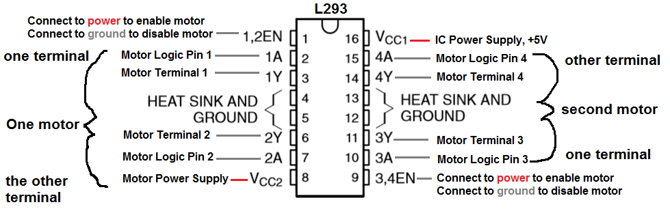
The L293/SN754410 is capable of controlling 2 motors.
It is a 4-channel H-bridge, meaning it can connect 4 terminal wires from motors. Since each motor has 2 terminals, it can control 2 motors (2x2=4).
Pin 1 is the enable pin for terminals 1 and 2. It enables motor to turn on when it is connected to a power. And disables the motor from functioning when connected to ground.
Pin 2 is the motor logic pin for terminal 1. This is the voltage level which one of the motor terminals receive. The logic level will determine what action the motor will take. This is one of the two logic levels that determines the function of the motor connected.
Pin 3 is the pin where we connect one of the terminals of the motor to.
Pin 4 and Pin 5 both get grounded.
Pin 6 is where we connect the other motor terminal to. This completes the 2-terminal connections necessary for a motor to be hooked up to the H-bridge IC.
Pin 7 is the motor logic pin for terminal 2. This is the second voltage signal we feed to the motor to determine the action the motor will take.
Pin 8 is the pin which receives the voltage needed to power on the motor. It is the motor power pin. This is the pin where we place the positive voltage of the power supply that will operate the DC motor. So if the motor is a 9V motor, then you will need to feed 9V into this pin. If the motor is a 12V motor, then you will need to feed 12V into this pin.
Pin 9 is the enable pin for terminals 3 and 4. It enables the motor to turn on when connected to power and disables the motor when connected to ground.
Pin 10 is the motor logic pin for terminal 3. This is one of the logic voltage signals that determines the action that the second motor will take.
Pin 11 is the pin where we connect one of the terminals of the second motor to.
Pin 12 and Pin 13 both get grounded.
Pin 14 is the pin where we connect the other terminal of the second motor to.
Pin 15 is the motor logic pin for terminal 4. It is the second voltage signal that we feed into the second motor to determine the action the motor will take.
Pin 16 is the pin which receives the voltage needed for power for the IC. It is the IC power pin. The IC needs just about 5V in order to operate.
Therefore, we feed 5V into this pin.
These are all the pins of the motor. Once power is supplied to the IC and the motor and all the terminals of the motor are connected, then the pins which determine how the motors will operate are the logic levels that we feed into it.
The logic levels determine what action the motor will take.
A breakdown of logic levels and the resultant motor action are shown in the table below.
| Enable | Logic Pin 1 | Logic Pin 2 | Result |
| High | Low | High | Forward |
| High | High | Low | Reverse |
| High | Low | Low | Stop |
| High | High | High | Stop |
| Low | Doesn't matter | Doesn't matter | Off |
When the enable pin is high and the motor is fed a LOW voltage signal at the first pushbutton and a HIGH voltage signal at the second pushbutton,
then
the motors will spin forward. When the enable is high and the motor is fed a HIGH voltage signal at the first pushbutton and a LOW voltage signal at the second
pushbutton, then
the motors will spin in reverse. And with both logic levels at the same level (2 HIGHs or 2 LOWs), then the motors will stop spinning.
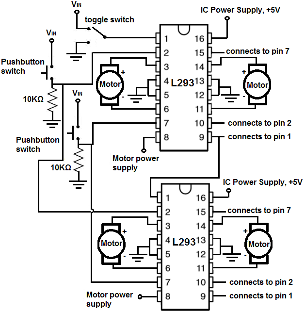
4-Motor H-bridge Circuit
The H bridge circuit we will build to control 4 motors is shown below.
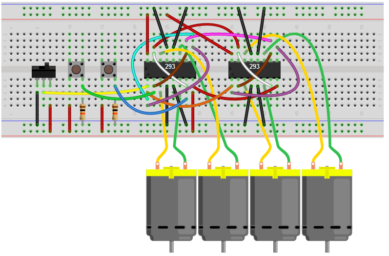
This above circuit built on a breadboard is shown below.
How this circuit works is based on the 2 switches that control the logic state and the 1 enable switch.
All the motor logic pins are tied together for each of the motors, so the 2 pushbuttons control the logic state for all the 4 motors. Thus, this is why they act in concert. So the first pushbutton controls the first logic state for each of the motors. And the second pushbutton controls the second logic state of each of the motors.
So with the motor logic pins normally LOW, if we press down on the second button while leaving the first one unpressed, then the motors will spin in a forward.
Now if we press down on the first pushbutton while leaving the second one unpressed, the motors will spin in the reverse direction.
If we leave both unpressed or press down on both simultaneously, the motors will not spin.
And this is all that is necessary for the operation of our 4-motor device.
To wire it up, it's pretty simple. For each chip, we connect terminals 1 and 3 and then
connect terminals 2 and 4. This way, both motors of
a chip are synched in together in a given chip. After this, for each additional chip we do the same, and then tie in
the the logic pins of the chip before into the chip after, so that all logic pins are connected together.
Related Resources
How to Build an H-bridge Circuit to Control 2 Motors
How to Build an H-bridge Circuit (with an L293 Chip)
How to Build an H-bridge Circuit with an Arduino Microcontroller
How to Build an H-bridge Circuit with Transistors