
How to Build an H bridge Circuit with Transistors
In this circuit, we will show how to build an H-bridge circuit with transistors.
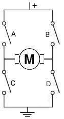
An h bridge is a circuit that is used primarily to control motors; they allow for forward and reverse motion of the motors. Therefore, the motor can be utilized with its full bidirectional capability.
To build an H-bridge, the only option is not to use an IC chip for an H-bridge. You can also build it with discrete and simple components such as with transistors and resistors.
Even though it's almost invariably simpler to use an IC to act as an H-bridge such as the popular L293 IC, there may be times you may want to design one yourself for any various reasons. You may also just be interested in knowning how an h bridge works.
So in this circuit, we will build an H-bridge simply with bipolar junction transistors.
Since motors run off a good amount of current, we will use high-current gain and high-power transistors. These are transistors provide very good current gain and transistors that deal with a lot of power.
In total, we use 4 different transistors, 2 PNP transistors and 2 NPN transistors.
The 2 types of transistors we will use are the TIP107 PNP transistors and the TIP102 NPN transistors. These are darlington transistors that can deal with high power outputs. Again, since motors require a good amount of current, normally about 75mA or so, we want a high-power transistor. Motors require several times more current than an output device that say an LED would. We will talk about these transistors more.
Know that h bridges are useful for circuits that require bidirectional functioning. Otherwise, the only way to be able to operate the device bidirectionally would be to manually switch the polarity leads of the device. An H-bridge eliminates this need.
So, again, h bridges can be used for any type of bidirectional 2-lead device
that works in opposite directional depending on which lead is connected to power.
It's mostly for motors, but it can also be for other devices as well.
Components
- 2 TIP107/127 PNP transistors
- 2 TIP102/120 NPN transistors
- 4 1KΩ resistors
- 2 5.6KΩ resistors
- DC motor
Really any NPN transistors or PNP transistors can be used. But it is better for them to be high-power transistors, since motors need adequate current.
The TIP107/127 transistors are PNP darlington transistors.
Being that they are a darlington transistors, they provide high current gain. They also can deal with high power. The collector of the TIP107 transistor can deal with up to 80 watts of power, while the TIP127 can deal with up to 65W.
Being that the highest-rated DC motors are normally 12V, this means that the collector can pass 6.7A. Obviously, the motor requires nothing close to this. We need less than 100mA. So this transistor is well above the same range in power that we need.
The datasheets for the TIP107 or the TIP127 can be found at the following links: TIP107 PNP Datasheet and TIP127 PNP Datasheet.
The TIP102/TIP120 transistors are NPN darlington transistors.
Being darlington transistors, they also provide high current gain. This is good so that they can drive a high-power device such as a motor. The transistors themselves can deal with high power.
The datasheets for the TIP102 or the TIP120 can be found at the following links: TIP102 NPN Datasheet and TIP120 NPN Datasheet.
Again, you can really use any NPN or PNP transistors. High-power ones are better for this circuit, as motors need more, but you can mix and match and see what works.
The DC motor can be any type, of really any voltage. We are using a 6-12V DC power supply, so the maximum rating the motor should have is 12V. Normally, anyway, DC motors aren't rated higher than 12V, so you can use practically any motor.
Besides these, all we need else are resistors.
H Bridge Circuit Built with Transistors
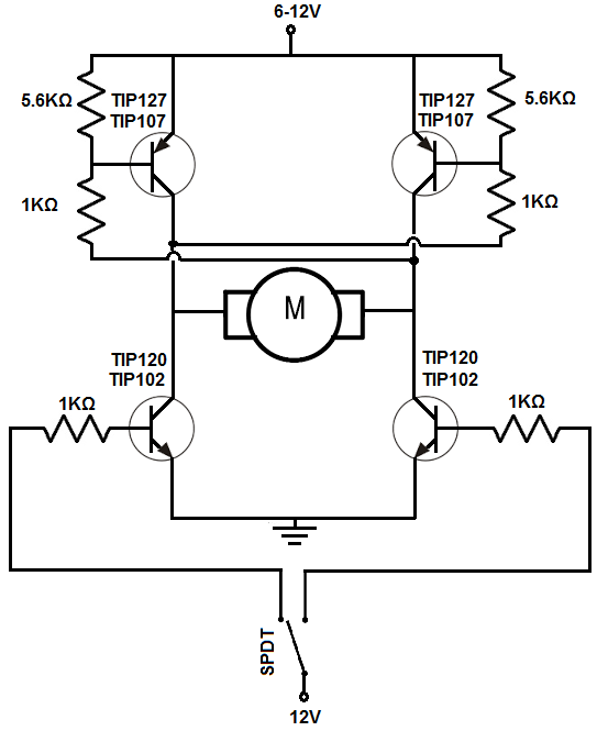
The h bridge circuit we will build with
4 bipolar transistors is shown below.
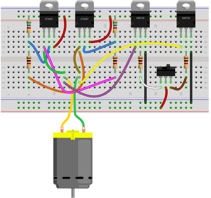
The breadboard circuit of the circuit above is shown below.
So the first thing that should be done is setting up power for the circuit. The circuit operates off of 6-12V, so it can run any type of motor. However, if you are using a much lower voltage-rated DC motor such as a 3V, you can use lower voltage.
The circuit is manually controlled through a single pole double throw (SPDT) switch, a toggle switch.
The positive voltage either powers the base of the transistor on the left or the right. This transistor that gets the positive voltage turns on.
This turns on the transistor on top on the other side.
Thus, if we turn on the left transistor, current flows from the right of the power source through the transistor on the top right, through the DC motor from right to left, and then from the left transistor to ground.
If we flip the toggle switch to the other side, the bottom right transistor will be powered on. This turns on the transistor at the top on the left side. Current flows from the power source, through the leftmost transistor at the top, through the DC motor, from left to right, and through the rightmost transistor and down to ground.
Therefore, the circuit functions as an H-bridge.
If the switch is flipped one way, the motor spins in one direction.
If the switch is flipped the other way, the motor spins in the other direction.
So the circuit is able to achieve bidirectionality of the motor, as an h bridge should.
Normally, we would put diodes in reverse biased across the transistors. These diodes would help dampen transient spikes that are generated by the motor's coils so that they do not damage other components in the circuits. When a transistor stops running, it can create reverse emf, transient voltage spikes that can be large. To prevent them, reverse biased diodes would stop these spikes from proceeding to other parts of the circuit, where they could cause damage. Being we're flipping the transistors on and off by flipping the toggle switch, you do want to have protection against back emf.
A SPDT switch is used for manual control to demonstrate how the circuit works. It is perfect because it only allows one of the NPN transistors to be on at any given time. Both transistors cannot be on at the same time because both transistors would have current flowing through, which is like a forbidden state. Therefore, it should be avoided. A SPDT switch avoids this condition.
The circuit, as is, will never be off unless the power supply is removed, being that the SPDT has no switch in which both transistors are grounded. To counter this, you could add a switch to the power supply so that the power supply disconnects from the circuit, if this is desired.
If you don't want the circuit to be manually controlled by a switch, you can remove the SPDT switch and instead connect the base of the NPN transistors to whatever device you want to control it, such as a microcontroller. You still keep the 1KΩ resistors at the base.
Another thing is that this circuit, as if, puts the DC motor at one speed. To vary the speeds, instead of inputting a fixed DC voltage to the base of the transistors, a pulse width modulated signal would be applied to the base. We won't get into this article what value of PWM signal you would need to achieve a given speed, but you can take this approach to vary the speed of the DC motor. This is a far more efficient way than using a potentiometer to vary the speed, which is inefficient since it creates large power waste, though you can still use it.
So this is how an h bridge circuit can be built with transistors.
To see how this circuit functions in real life, see the following video below.
Related Resources
How to Build a Modified Window Comparator Circuit