
How to Build an H-bridge Circuit with an Arduino Microcontroller
An h-bridge is a chip that allows DC motors to be run versatile, with bidirectional capability. With an H-bridge, motors can go forward or backward, left or right, up or down, etc, depending on the use of the motor(s) in the circuit.
Without a microcontroller, the only way to be able to control an H-bridge is through multiple switches. We would need a switch tied to the enable pin of the H-bridge (unless it's permanently enabled by being connected to power) and another 2 switches tied to the logic pins of the H-bridge, assuming we are connecting only one motor. Thus, we would have to have this network of switches with an H-bridge if we are using a microcontroller.
With a microcontroller such as the Arduino, we can do away with most of the switches. We no longer would need switches connected to the logic pins of the H-bridge, because the microcontroller through sofware can send the logic levels to the logic pins. So we no longer have to manually manipulate switches to control logic levels. We also no longer need a switch to the enable pi. Because this can be controlled through software programming so that we can decide whether the enable pin is on (connected to power) or off (connected to ground).
With our microcontroller circuit, we only use one switch and that is to decide whether the motor runs forward or in reverse, left or right, etc. If the switch is one way, the motor will spin in a certain direction. If the switch is flipped, the motor will spin in the opposite direction. This way, the user can decide which direction he or she wants the motor(s) to spin. This is the only switch we will use.
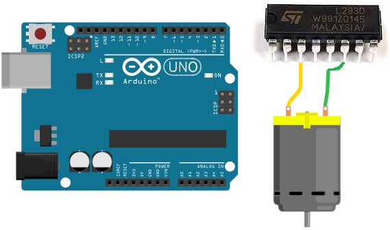
For our microcontroller, we will use an Arduino and connect it to a L293 H-bridge chip.
Connecting an H-bridge chip to a microcontroller such as the Arduino isn't too complicated and doesn't have
too many connections. We will show exactly how to connect so that we can control motors and allow for bidirectional movement
through code.
Components Needed
- L293/SN754410 H-bridge Chip
- DC Motor
- Toggle Switch
- Power Source
The L293/SN754410 H-bridge chip is 16-pin chip that can be used to drive and control inductive loads such as relays, solenoids, DC motors, and bipolar stepper motors.
However, in this project, we will be using a DC motor with the L293.
The L293/SN754410 is a relatively inexpensive chip that can be obtained for a little over $1. One place that sells the L293 is Tayda Electronics- L293 Driver IC.
Before we build this circuit, you must understand the chip and all of its pin connections. You must always know pin connections when hooking up any chip.
Overall, the L293/SN754410 chips aren't very as complicated as they may seem. They both have identical pinouts.
The pinout of the L293/SN754410 is shown below.
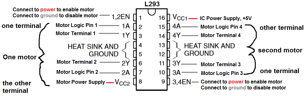
The L293/SN754410 is capable of controlling 2 motors.
It is a 4-channel H-bridge, meaning it can connect 4 terminal wires from motors. Since each motor has 2 terminals, it can control 2 motors (2x2=4).
Pin 1 is the enable pin for terminals 1 and 2. It enables motor to turn on when it is connected to a power. And disables the motor from functioning when connected to ground.
Pin 2 is the motor logic pin for terminal 1. This is the voltage level which one of the motor terminals receive. The logic level will determine what action the motor will take. This is one of the two logic levels that determines the function of the motor connected.
Pin 3 is the pin where we connect one of the terminals of the motor to.
Pin 4 and Pin 5 both get grounded.
Pin 6 is where we connect the other motor terminal to. This completes the 2-terminal connections necessary for a motor to be hooked up to the H-bridge IC.
Pin 7 is the motor logic pin for terminal 2. This is the second voltage signal we feed to the motor to determine the action the motor will take.
Pin 8 is the pin which receives the voltage needed to power on the motor. It is the motor power pin. This is the pin where we place the positive voltage of the power supply that will operate the DC motor. So if the motor is a 9V motor, then you will need to feed 9V into this pin. If the motor is a 12V motor, then you will need to feed 12V into this pin.
Pin 9 is the enable pin for terminals 3 and 4. It enables the motor to turn on when connected to power and disables the motor when connected to ground.
Pin 10 is the motor logic pin for terminal 3. This is one of the logic voltage signals that determines the action that the second motor will take.
Pin 11 is the pin where we connect one of the terminals of the second motor to.
Pin 12 and Pin 13 both get grounded.
Pin 14 is the pin where we connect the other terminal of the second motor to.
Pin 15 is the motor logic pin for terminal 4. It is the second voltage signal that we feed into the second motor to determine the action the motor will take.
Pin 16 is the pin which receives the voltage needed for power for the IC. It is the IC power pin. The IC needs just about 5V in order to operate.
Therefore, we feed 5V into this pin.
These are all the pins of the motor. Once power is supplied to the IC and the motor and all the terminals of the motor are connected, then the pins which determine how the motor will operate are the logic levels that we feed into the motor.
The logic levels determine what action the motor will take.
A breakdown of logic levels and the resultant motor action are shown in the table below.
| Enable | Logic Pin 1 | Logic Pin 2 | Result |
| High | Low | High | Forward |
| High | High | Low | Reverse |
| High | Low | Low | Stop |
| High | High | High | Stop |
| Low | Doesn't matter | Doesn't matter | Off |
When the enable pin is high and the motor is fed a LOW voltage signal at the first terminal and a HIGH voltage signal at the second terminal, then it will spin forward. When the enable is high and the motor is fed a HIGH voltage signal at the first terminal and a LOW voltage signal at the second terminal, then it will spin in reverse. And with both logic levels at the same level (2 HIGHs or 2 LOWs), then the motor will stop spinning.
And this is how motor function will work.
Arduino Microcontroller H-bridge Circuit
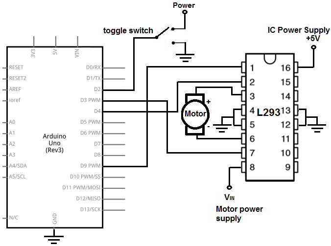
The Arduino microcontroller H bridge circuit we will build is shown below.
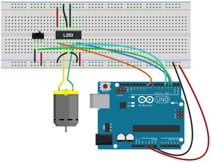
This above circuit built on a breadboard is shown below.
How this circuit works is based on a single switch, the toggle switch.
The toggle switch controls the direction that the motor will spin.
If flipped to the other side, the direction that the motor spins will be opposite. So it controls the forward/backward or left/right movement of the
motor. In the software code, which is shown below, we make it so that the toggle switch controls this direction.
Code
The code needed to operate this H-bridge circuit with an Arduino is shown below.
const int toggleSwitch = 2;
const int motorTerminal1 = 3;
const int motorTerminal2 = 4;
const int enablePin = 9;
void setup() {
pinMode(toggleSwitch, INPUT);
pinMode(motorTerminal1, OUTPUT);
pinMode(motorTerminal2, OUTPUT);
pinMode(enablePin, OUTPUT);
digitalWrite(enablePin, HIGH);
}
void loop() {
if (digitalRead(toggleSwitch) == HIGH) {
digitalWrite(motorTerminal1, LOW);
digitalWrite(motorTerminal2, HIGH);
}
else {
digitalWrite(motorTerminal1, HIGH);
digitalWrite(motorTerminal2, LOW);
}
}
The first block code establishes all the pin connections of the H-bridge to the Arduino.
The next block of code, the setup() function, defines the inputs and outputs. The only input to the circuit is the toggle switch. The rest of the pins, including the motor terminals and the enable pin, are outputs. We then write the digital value of HIGH to the enable pin, so that it is permanently enabled through software.
The last block of code, our loop() function, which is the function that executes over and over again, makes it so that if the
toggle switch is flipped one way, the motor will spin in one direction and if it's flipped the other way,
the motor will spin in the opposite direction. The digitalRead() function reads the value from the toggle switch to determine if it is HIGH or LOW.
If HIGH, it will send the logic levels of LOW for motor terminal 1 and HIGH for motor terminal 2; this gives forward direction. If LOW, it will send logic levels of
HIGH for motor terminal 1 and LOW for motor terminal 2; this gives reverse direction.
And this is how a microcontroller such as the arduino can control motors through an H-bridge IC.
Related Resources
How to Build an H-bridge Circuit to Control 2 Motors
How to Build an H-bridge Circuit to Control 4 Motors
How to Build an H-bridge Circuit (with an L293 Chip)
How to Build an H-bridge Circuit with Transistors