
How to Build an Accelerometer Circuit
In this article, we go over how to build a basic accelerometer circuit.
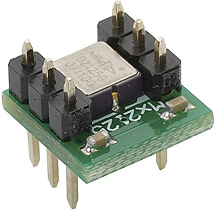
The type of accelerometer we will use is a memsic 2125 accelerometer.
As you are probably familiar, an accelerometer is a device that can measure dynamic acceleration (vibrations) and static acceleration (gravity). Being that it measures this, it can measure tilts, rotations, and movements/lack-of-movements for alarm system sensing. Basically, it can measure if it's being tilted, rotated, or moved around.
Being that an accelerometer measures tilts, it needs a microcontroller to be able to read these tilts and record how much it is tilted. The microcontroller we will connect to the accelerometer is an arduino microcontroller.
Tilts and imbalances on accelerometers are measured in unit millig's. A millig (mg) is a 1/1000th of a g. Being that the g-force is equal to 9.81m/s2, a millig is equal to 1/1000th of this value.
The memsic 2125 is a dual- or two-axis accelerometer. It can measure tilts
in the 2 directions, the X-direction and the Y-direction. This means that if we shift it
left and right, this is the X-direction. If we shift it forward or backward, this is teh
Y-direction. The memsic is able to record these movements and then the arduino can
sense and output to us the data.
Components Needed for Accelerometer Circuit
- Memsic 2125 Accelerometer
- Arduino Board
- Breadboard
- Jumper Wires
- 5 volts
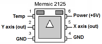
Memsic Accelerometer Pinout
Before we go into the main circuit schematic, we will first go over
the pinout of the memsic 2125 accelerometer.
| Pin number | Pin name | Description |
| Pin 1 | Temperature Out | The memsic acceleraterometer can also give the a temperature reading out. To give out the temperature, this pin would be connected to a microcontroller, which would then be able to read and display out the temperature. |
| Pin 2 | Y axis (out) | The Y axis (out) pin gives out the reading of the Y axis. Thus, if the accelerometer is tilted in the Y direction, then the accelerometer can give out the tilt reading in millig's so that the microcontroller it is connected to can know how the accelerometer is tilted in the Y direction. |
| Pin 3 | Ground | This pin connects to ground of the circuit. |
| Pin 4 | Ground | This again connects to ground of the circuit. |
| Pin 5 | X axis (out) | The X axis (out) pin gives out the reading of the X axis. Thus, if the accelerometer is tilted in the X direction, then the accelerometer can give out the tilt reading in millig's so that the microcontroller it is connected to can know how the accelerometer is tilted in the X direction. |
| Pin 6 | Power (+5V) | Memsic 2125 needs +5V of DC power in order to operate. Pin 4 is where the memsic receives its operating DC voltage in order to work. |
For this project, we are not going to use Pin 1, the temperature out reading.
Accelerometer Circuit Schematic
The accelerometer circuit we will build is shown in the schematic below:
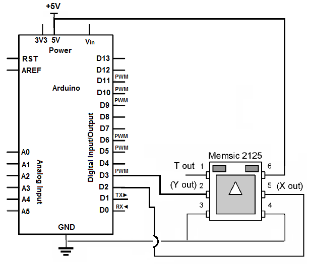
To connect the accelerometer, we give it +5VDC of power. Accelerometers need power in order to operate. We connect both GND pins to GND. These are Pins 3 and 4. Then we connect Pin 2, Y OUT, to D3 of the arduino. We connect Pin 5, X OUT, to D2 of the arduino. Terminals D3 and D2 of the arduino are digital input pins, which receive the digital readings that the accelerometer gives out, showing its X and Y axis tilt readings.
Now that we have connected the circuit, we now need to create a program
which calculates the millig readings and can display to us on the computer so that we
can know all the readings that go on as the accelerometer is tilted.
Code to Read and Display Accelerometer Tilt Readings
const int xPin = 2; // X output of the accelerometer
const int yPin = 3; // Y output of the accelerometer
void setup() {
Serial.begin(9600);
// as inputs:
pinMode(xPin, INPUT);
pinMode(yPin, INPUT);
}
void loop() {
int pulseX, pulseY;
int accelerationX, accelerationY;
pulseX = pulseIn(xPin,HIGH);
pulseY = pulseIn(yPin,HIGH);
// accelerationX and accelerationY are in milli-g's:
// earth's gravity is 1000 milli-g's, or 1g.
accelerationX = ((pulseX / 10) - 500) * 8;
accelerationY = ((pulseY / 10) - 500) * 8;
Serial.print(accelerationX);
Serial.print("\t");
Serial.print(accelerationY);
Serial.println();
delay(100);
}
Once we put this code in the arduino processing software and run the code, we will get out all the readings of the X and Y axes. If we tilt the accelerometer in the X direction, the milli-g's reading will be much greater of the X axis. If we tilt the accelerometer in the Y direction, the milli-g's reading of the Y axis will be much greater.
Accelerometers are important because they measure this tilt. If we have an electronic device that can only sustain a certain amount of tilt, we can w
write code so that if it tilts more than a certain amount of milli-g's, an event can occur. For example, if a user tilts an electronic device more than 900 milli-g's,
a siren will loud. We can connect a siren to a digital output pin of the arduino. We can then write code so that if there is a tilt greater than 900 milli-g's, the siren
will be turned on. So this is the tremendous application that accelerometers have. They measure tilt so that an event can be triggered if a device gets too much off balance.
Related Resources
How to Build a Hall Effect Sensor Circuit
How to Build a Motion Detector Circuit
How to Build a Vibration Detector Circuit