
How to Build an Active Low Pass Filter Circuit with an Op Amp
In this project, we will show how to build an active low pass filter with an op amp and a few simple components comprised of resistors and a capacitor.
An active low pass filter is a filter that amplifies low-frequency signals and allows them to pass through to output but greatly attenuates high-frequency signals.
In contrast, an active high pass filter amplifies high-frequency signals and allows them to pass through to output and greatly attenuates low-frequency signals.
In an active low pass filter, the peak of the passband of the filter can be much larger than the input voltage signal because there is amplification.
For passive low pass filters to be built, all that is required are resistors and capacitors.
Active low pass filters require either transistors or op amps to provide amplification to the circuit.
Op amps are more likely more used, as they are easier to bias.
With an active op amp filter, we can design the circuit so that we can determine the gain and the cutoff frequency of the low pass filter.
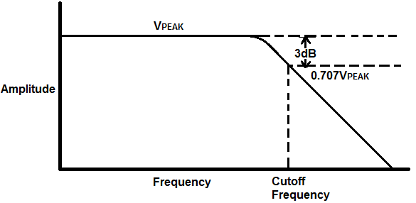
How the circuit works is the circuit will pass signals with full or near full strength strength below the frequency cutoff point and ngreatly attenuate signals above the frequency cutoff point. So, for example, if the low-pass filter is designed for 1KHz, the circuit will output signals under 1KHz full to near full strength. Signals greater than 1KHz will be greatly attenuated, so that their amplitudes are much less than the amplitude of signals in the passband. The passband refers to the signals that are passed through to output. In this example, the passband would be from 0Hz to 1KHz.
The frequency cutoff point is the point in the circuit in which there is a 3dB drop in amplitude. A 3dB drop equals 0.707VPEAK. If you look at the low pass filter graph shown above, there is a peak amplitude, VPEAK. Then as you get to the , the amplitude drops. When it reaches 0.707VPEAK, this is the 3dB cutoff point. The 3dB cutoff point represents half the maximum power.
After the 3dB cutoff point, there is a steep drop in amplitude, so frequencies outside of the cutoff frequencies are greatly attenuated.
And this is how a low pass filter works.
We will use the standard, very popular LM741 op amp chip to build our circuits.
We choose this because it's very popular, very wide used, and it can get the job done for this circuit. We don't need any advanced or more expensive op amps.
We will show in this circuit how an active low pass filter can be constructed either to be an inverting low pass filter or a noninverting low pass filter.
Usually, for circuit sake, it normally doesn't matter if it's inverting or noninverting but for demonstration purposes, we will show how to build either one
so that in case it's important that the output is noninverting or inverting, we will show how it's done.
Components Needed
- 47nF capacitor
- 1.5KΩ resistor
- 15KΩ resistor
- 1KΩ resistor
- 9KΩ resistor
So the chip we will use again is an LM741 operational amplifier chip.
The LM741 chip is composed of a single op amp.
It is an 8-pin chip.
We will only use 5 of the pins in our circuit.
Pins 7 and 4 are the power pins. Pin 7 is where we connect positive DC voltage to and pin 4 we connect to negative voltage.
Pins 2 and 3 are the input pins to the op amp. Pin 2 is the inverting terminal and pin 3 is the noninverting terminal.
As stated above, we will show how to create the low pass filters to allow for a noninverting output and an inverting signal.
Pin 6 is the ouput of the op amp.
And these are the only 5 pins we use, so it's pretty simple.
Apart from the L741 op amp, we just need resistors and capacitors.
In this circuit, we make the low pass filter so that the cutoff frequency is about 226Hz. So the passband is any frequency below the 226Hz point.
However, if you are modifying
this circuit so that there is a different passband, then you would need to modify the values of the components. We show below
to compute the frequencies so that you can create any passband. But it's not infinite because you still have to take into account the capabilities of the op amp,
such as the maximum voltage it can handle as well as the op amp's slew rate. We discuss this more in depth below.
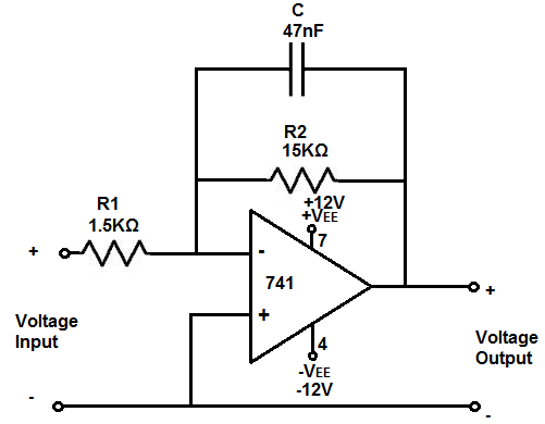
Active Inverting Op Amp Low Pass Filter Circuit
The inverting low pass filter circuit that we will build with an LM741 op amp chip and a few resistors and a capacitor is shown below.
This low pass filter below is an inverting low pass filter.
This means that the output of the op amp is 180 degrees of out of phase with the input signal. This correlates, from an image angle, vertically flipping the input signal and this what would appear as output.
So now this will be explained in thorough detail.
So first thing is powering the op amp. The op amp requires DC power in order to operate. The amount DC power is that is needed depends on how large the amplified output signal will be. The output AC voltage signal will only be as high as the ceiling and floor. And the ceiling and floor fo the AC signal is set by the DC power line. What is meant by this is that the AC signal can only be as high as the DC floor that is set. If the output AC signal is, for example, 20V peak to peak, the DC voltage fed into pin 7, V+, must be 10VDC or higher and the DC voltage fed into pin 4, V-, must be -10VDC or lower. These levels allows the AC signal to be able to swing from up to +20V down to -20V. So the DC signal sets the amount of room that the AC signal is able to swing.
In order for the circuit to work properly, pin 4, V-, must be connected to negative voltage. It can't be connected to ground. If connected to ground, the AC signal will swing from the peak of the voltage down to 0V, meaning the negative portion of the AC signal will be clipped.
So, in our circuit, we design the low pass filter so that it has a gain of 10. We feed +12VDC into V+, pin 7, of the op amp and -12VDC into V-, pin 4. Being that the ceiling is +12V and the floor is -12V, the maximum input signal that can be fed into the op amp is 1.2V. Any signal greater than this will produce clipping and distortion, since 12V/10= 1.2V. However, you don't want to make it so that it's exactly on the line like this because the op amp isn't ideal. It may have some slight DC offset. Even if you operated the op amp to remove DC offset, it still will have some DC offset; therefore, you shouldn't set the input signal so that it's exactly on the ceiling and floor. Therefore, for all practical purposes to remove clipping and, thus, distortion, the maximum input signal should be about 1.1V or so.
So now the DC supply voltage to the op amp is explained and why it's so important, let's get to the heart of the low pass filter.
So the part of the circuit composed of resistor R and capacitor C form the low pass filter.
The formula for calculating the cutoff frequency is, frequency= 1/2πR2C= 1/2π(15KΩ)(47nF)= 225.8Hz≈ 226Hz.
So we use a 15KΩ resistor with a 47nF capacitor to form this 226Hz cutoff frequency point.
The gain of the op ap is determined by resistors resistors R1 and R2 by the formula, gain (AV)= -R2/R1.
Since R2 is 10 times greater than R1, the gain is -10.
The negative means that the voltage output is inverted from the voltage input. So while the input voltage is +10V, the output voltage is -10V. They're 180 degrees out of phase. When one is at the positive peak, the other is at its negative peak. A full AC signal is 360 degrees.
Usually phase does not matter. Unless you're dealing with a phase-critical application, it shouldn't matter whether the low pass filter is inverting or noninverting. Phase may only be critical if you need the output signal to be in synch with the input signal (noninverting) or if you need the output signal to be in opposite synch with the input signal (inverting), such as in the case of flasher circuit or motor circuit (pwm modulation).
If this doesn't apply, then it doesn't matter whether it's inverting or noninverting.
The inverting circuit is a little easier to build than the noninverting terminal.
Active Noninverting Op Amp Low Pass Filter Circuit
The noninverting low pass filter we will build with an LM741 op amp is shown below.
This allows the input signal and output signal to be in phase with one another.
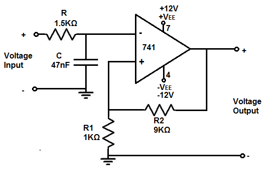
So the first part of the circuit composed of R and C form the low-pass filter. It passes all frequencies below the point it is designed to pass.
The signal is then amplified by the op amp by a gain proportional to resistors R2 and R1 according to the formula, gain (AV)= 1 + R2/R1. Since R2 is 9KΩ and R1 is 1KΩ, the gain is 10.
After being amplified, the signal then passes through the low-pass filter. The low-pass filter is composed of a 1.5KΩ and 47nF capacitor, which sets a cutoff frequency of 2.2KHz. So it passes all frequencies below this value.
And this is the circuit that gives an amplified noninverting signal. So the input signal and the output signal are in phase.
Regardless of which circuit you choose to build, inverting or noninverting, you must watch out for a few things.
One of the first things to take into account is the maximum DC voltage power supply the op amp can deal with.
The maximum DC voltage that the LM741 can handle is ±22V or ±18V for the LM741C.
This is important because it sets the maximum peak to peak AC voltage that the op amp can output.
If the maximum DC voltage the op amp can handle is ±22V, this means that the AC voltage can swing to a maximum of 44VPEAK-to-PEAK. It can have a peak positive voltage of +22V and a peak negative voltage of -22V.
The other factor that must be taken into account is the op amp's slew rate. The slew rate is how fast the op amp can output voltage per unit time. The slew rate is determined by the formula, slew rate= 2πfV.
The slew rate is normally specified as voltage per unit time, specifically voltage per microseconds. So the slew rate is how many volts the op amp can output per microsecond. The slew rate largely shows how high-speed an op amp is. Op amps are higher speed, meaning they can output voltage at a quicker rate, have higher slew rate values.
An LM741 has a slew rate of 0.5V/µs. Other very high-speed op amps can have slew rates as high as 6000V/µs.
But going back to the LM741, it has a slew rate of 0.5V/µs.
Inputting this into the slew rate formula, the LM741 can output 1V at a frequency of 79,617Hz. Doing the math, we first convert the slew rate to volts per second. To convert the slew rate from volts per microsecond to volts per second, we take the slew rate voltage and divide it by 0.000001 to give us seconds. So 0.5V/0.000001= 500,000V/s. We can now plug it into the formula, slew rate= 2πfV= 500,000= 2(3.14)(1V)(f). This is if you are outputting 1V peak to peak.
We are obviously going to output more voltage. If you are outputting 10V peak-to-peak, the maximum frequency at which this can be done for the LM741 op amp is 7961Hz.
If you are outputting 20V peak-to-peak, the maximum frequency at which this can be done for the LM741 op amp is 3980Hz.
If you are outputting 30V peak-to-peak, the maximum frequency at which this can be done for the LM741 is 2653Hz.
If you are outputting the maxium 44V peak-to-peak, the maximum frequency at which this can be done for the LM741 op amp is 1809Hz.
So as you can see, there a number of factors that go into creating a low pass filter with an op amp. If you are dealing with high-frequency signals, then it's best to use a much higher-speed op amp than the LM741. For relatively low frequencies, it should suffice.
And this is how a low pass filter circuit can be an op amp.
Related Resources
Bandpass Filter Calculator
How to Build a Passive Bandpass Filter Circuit
How to Build an Active Bandpass Filter Circuit with an Op Amp
How to Build an Active High Pass Filter Circuit with an Op Amp