
Bandpass Filter Calculator
Passive Bandpass Filter
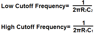
Passive Bandpass Filter Formulas
This page contains 3 bandpass filter circuits.
The first bandpass filter circuit is for a passive bandpass filter composed of just resistors and capacitors.
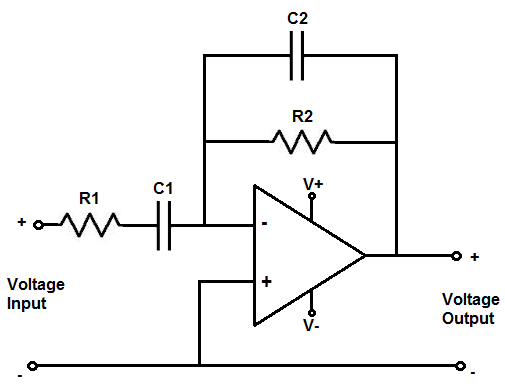
The second bandpass filter circuit is for an active bandpass filter composed of an op amp that gives an amplified inverting output. This means that the output signal is 180 degrees out of phase from the input voltage signal.
The third bandpass filter circuit is for an active bandpass filter composed of an op amp that gives an amplified noninverting output. This means that the output signal is exactly in phase with the input voltage signal.
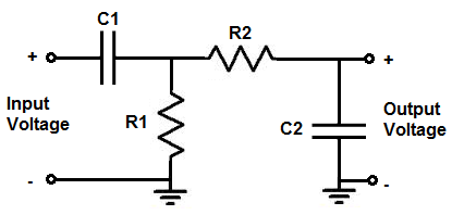
So, on to the first bandpass filter circuit, shown above, that shows a passive bandpass filter composed of 2 resistors and 2 capacitors.
A passive bandpass filter is a bandpass filter that does not require power and does not give amplification of the input signal.
On the contrast, an active bandpass filter is a bandpass filter that requires power and amplifies the input signal.
The passive bandpass filter, shown above, is first composed of a high-pass filter shown by resistor R1 and capacitor R2.
The high-pass filter forms the low cutoff frequency.
What the high-pass filter does is it passes all frequencies above the low cutoff frequency point.
The formula for calculating the low cutoff frequency is, frequency= 1/2πR1C1
The next part of the circuit is the low-pass filter.
The low-pass filter forms the high cutoff frequency.
What the low-pass does is it passes all frequencies below the high cutoff frequency point.
So the high-pass filter passes all frequencies above the low cutoff frequency point and the high-pass filter passes all frequencies below the high cutoff frequency point.
The formula for calculating the high cutoff frequency is, frequency= 1/2πR2C2
All the frequencies in between these 2 cutoff frequency points form the passband of the bandpass filter circuit. The passband are the frequencies that are passed to the output without much attenuation. All other frequencies outside the cutoff frequencies are greatly attenuated. The further the frequency is from the passband, the more it is attenuated.
So, for example, if the low cutoff frequency point is 1KHz and the high cutoff frequency point is 10KHz, the passband is from 1KHz to 10KHz. These frequencies pass through without much attenuation. Frequencies outside the passband are greatly attenuated such as those below the low cutoff frequency such as 500Hz, for example, or those above the high cutoff frequency such as 20KHz, for example.
So to use the passive bandpass calculator, all you have to enter is the low cutoff frequency point, or the minimum frequency desired to be passed, and the high cutoff frequency point ,or the maximum frequency desired to be passed. The calculator will then compute the values of resistor R1, capacitor C1, resistor R2, and capacitor C2.
The calculator allows for you to specify whether the frequency is in hertz, kilohertz, or megahertz for
each of the cutoff frequencies.
Active Inverting Op Amp Bandpass Filter
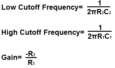
Active Inverting Op Amp Bandpass Filter Formulas
This calculator is an active inverting bandpass filter calculator.
The output is the inverted input signal, which means the input signal and output signal are 180 degrees out of phase. When one is on, the other off.
This active bandpass filter is composed first of a high-pass filter which is made up of resistor R1 and capacitor C1.
Resistor R1 and capacitor C1 set the low cutoff frequency for the bandpass filter.
All frequencies above this cutoff frequency point are passed through to output.
The formula for calculating the low cutoff frequency is, frequency= 1/2πR1C1
The second part of the circuit is composed of resistor R2 and capacitor C2, which forms the low pass filter.
Resistor R2 and capacitor C2 set the high cutoff frequency for the bandpass filter.
All frequencies below this cutoff frequency points are passed through to output.
The formula for calculating the high cutoff frequency is, frequency= 1/2πR2C2
So all frequencies between the low cutoff frequecny and the high cutoff frequency are the passband of the bandpass filter.
The gain of the circuit is determined by the formula, gain (AV)= -R2/R1. Thus, for example, to have a gain of 10, R2 must be 10 times the value of R1.
So to use this calculator, a user should has to specify the low cutoff frequency, the high cutoff frequency, and the gain of the circuit. The calculator will then compute the values of resistor R1, capacitor C1, resistor R2, and capacitor C2.
An important rule to keep in mind for this calculator if you are using a specific op amp is that you have to consider the op amp's specification when building the circuit.
The 2 specifications of the op amp that must be considered are the maximum DC voltage that can be supplied to the power rails of the op amp and the slew rate of the op amp.
First, you must know the maximum DC voltage that the op ap can handle at the power pins. This will allow us to know the maximum voltage that the AC voltage can swing from peak to peak. If, for example, the maximum DC voltage that the op amp can handle is ±18V, this means that the maximum AC voltage that the op amp can output is 36 volts peak to peak, or 18V peak. The AC voltage can only go as high as the DC rail. So if we feed +18V into V+ and -18V into V-, the AC voltage can swing as high as +18V and as low as -18V, which is 36 volts peak to peak. So the maximum DC voltage shows the maximum AC voltage it can show. If the AC voltage is larger than the DC rail, there will be clipping and distortion in the output signal.
The other factor is the op amp's slew rate. The op amp's slew rate is how fast the op amp can output voltage per a given unit of time. If the voltage is too large for a given frequency, the op amp may not be able to keep up and it will produce distorted. The slew rate of the op amp allows you to calculate the amount of voltage the op amp can output for a given frequency.
Slew rates range widely from op amp to op amp. The LM741 op amp has a slew rate of 0.5V/μS. High-speed op amps can have slew rates up to 6000V/μS.
How you can calculate if the op amp can handle a certain voltage at a certain frequency is determined by the formula, slew rate= 2πfV. The best way to do it is to convert the slew rate from volts per microsecond to volts per second. You do this by dividing the voltage by 0.000001 (a microsecond). Using the LM741's slew rate of 0.5V/μS, this would be 500,000V/s. We then plug this into the slew rate formula, slew rate= 2πfV= 500,000= 2(3.14)f(10V)= 7961Hz. So the op amp can output 10V at a maximum frequency of 7961Hz. Any frequency above this at 10V and the op amp won't be able to keep up with the output voltage. The frequency would be too fast for that voltage. Therefore, the op amp wouldn't be able to output that amplitude of voltage at that speed (frequency). So the slew rate must definitely be considered when creating this circuit.
If you are using relatively high frequencies, you will need a high-speed op amp.
Active Noninverting Op Amp Bandpass Filter
Active Noninverting Op Amp Bandpass Filter Formulas
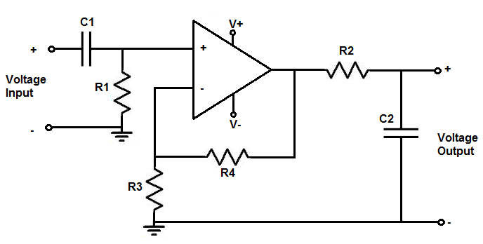
This calculator is for an active noninverting op amp bandpass filter.
Thi op amp bandpass filter produces a noninverting signal at the output. This means that the output signal is exactly in phase with the input signal.
The first part of this circuit comprised of resistor R1 and capacitor C1 compose the high-pass filter.
The high-pass filter forms the low cutoff frequency point in the circuit.
All frequencies above this cutoff point are passed to output.
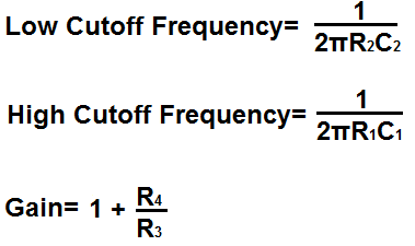
The formula for calculating the low cutoff frequency is, frequency= 1/2πR1C1
The resistor R2 and capacitor C2 form the low-pass filter.
The low-pass filter forms the high cutoff frequency point in the circuit.
All frequencies below this cutoff point are passed to output.
The formula for calculating the high cutoff frequency is, frequency= 1/2πR2C2
The resistor R3 and resistor R4 determine the gain of the circuit. The gain of the circuit is determined by the formula, gain (AV)= 1+ R4/R3.
For this calculator, a user just has to enter the low cutoff frequency, the high cutoff frequency, and the gain desired. The calculator will then compute the resistor R1, capacitor C1, resistor R2, capacitor C2, resistor R3, and resistor R4.
Just as with the other op amp bandpass filter circuit, the specifications of the op amp must be considered.
Related Resources
Low Pass Filter Calculator
High Pass Filter Calculator
Center Frequency Calculator
Notch Filter Calculator
Quality Factor Calculator
How to Build a Passive Bandpass Filter Circuit
How to Build an Active Bandpass Filter Circuit with an Op Amp
How to Build an Active High Pass Filter Circuit with an Op Amp
How to Build an Active Low Pass Filter Circuit with an Op Amp
Colpitts Oscillator Calculator
Hartley Oscillator Calculator
LC Resonance Calculator