
How to Build a Passive Bandpass Filter Circuit
In this project, we will show how to build a passive bandpass filter simply with resistors and capacitors.
A bandpass filter is a circuit that passes only a certain range of frequencies. All frequencies outside of this range are greatly attenuated.
A bandpass filter is needed if only a certain range of frequencies are needed. An example of uses for bandpass filters are audio applications if only certain frequencies are desired to be heard while others should not.
This type of bandpass filter is a passive bandpass filter. It doesn't require any power. It is not used for any active amplification. For active bandpass filters, ones that require power and usually provide amplification, op amps are normally used. Passive bandpass filters can be used in addition to an active circuit to provide amplification, if desired. But by itself a passive bandpass filter does not provide amplification.
The bandpass filter we will construct is really a combination of a high-pass filter and a low-pass filter.
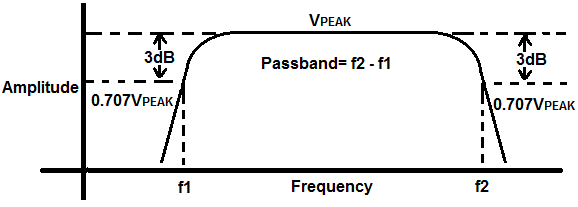
How the circuit works is the circuit will pass signals with full strength in between the frequencies of the low pass filter and the high pass filter. So, for example, if the low-pass filter is designed for 2KHz and the high-pass filter is designed for 200Hz, the circuit will output signals between 200Hz and 2KHz with full strength or near full strength. Signals outside of these frequencies will be greatly attenuated, so that their amplitudes are much less than the amplitude of signals in the passband. The passband refers to the signals in between the low and high pass filters that are passed with full strength. In this example, the passband is 200Hz-2KHz. The low cutoff frequency would be 200Hz and the high cutoff frequency would be 2KHz.
The low cutoff and high cutoff frequenices are the 2 points in the passband in which there is a 3dB drop in amplitude. A 3dB drop equals 0.707VPEAK. If you look at the bandpass graph shown above, there is a peak amplitude, VPEAK. Then as you get to the low and high cutoff frequencies, the amplitude drops. When it reaches 0.707VPEAK, this is the 3dB cutoff point. The 3dB cutoff point represents half the maximum power.
After the 3dB cutoff points, there is a steep drop in amplitude, so frequencies outside of the cutoff frequencies are greatly attenuated.
And this is how a bandpass filter works.
Components Needed
- 1nF capacitor
- 1μF capacitor
- 150Ω resistor
- 16KΩ resistor
Only we need are resistors and capacitors to build this circuit.
Below we show how to work out the math for this circuit, so that in the end you can choose what frequencies comprise the passband of the bandpass filter circuit.
For this circuit, with the values chosen, we build a bandpass filter that has a passband from 1KHz to 10KHz.
If modifying these frequencies, then the values of the resistors and capacitors need to change.
Passive Bandpass Filter Circuit
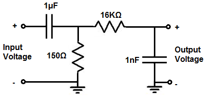
The passive bandpass filter circuit that we will build with resistors and capacitors is shown below.
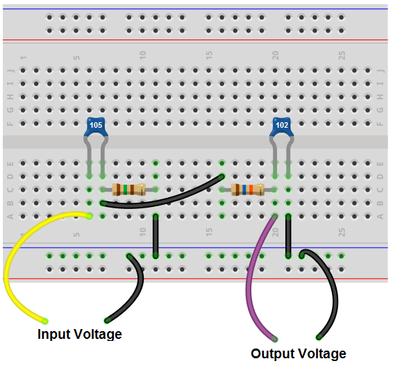
The breadboard circuit of the circuit above is shown below.
So the first part of the circuit composed of R1 and C1 form the high-pass filter. It passes all frequencies above the point it is designed to pass.
The high-pass filter design creates the lower cutoff frequency point. In the circuit, we want the lower cutoff frequency point to be 1KHz. Therefore, the high-pass filter passes all frequencies above 1KHz.
The formula for calculating the lower cutoff frequency is, frequency= 1/2πR1C1= 1/2π(150Ω)(1μF)= 1061 Hz≈ 1KHz.
So we use a 150Ω resistor with a 1μF capacitor to form the high-pass filter. These values give us a lower cutoff frequency of 1KHz.
The high-pass filter passes all frequencies above 1KHz and blocks all frequencies or greatly attenuates all frequencies below this point of 1KHz.
The second part of the circuit is composed of resistor R2 and capacitor C2. These form the low-pass filter. The low-pass filter blocks all frequencies below the cutoff point they are designed to.
In the circuit, we want the higher cutoff frequency point to be 10KHz. So the low-pass filter allows all frequencies below 10KHz to be passed through and blocks or greatly attenuates all frequencies above this 10KHz point.
The formula for calculating the lower cutoff frequency point is the same as the high cutoff frequency, frequency= 1/2πR1C1= 1/2π(16KΩ)(1nF)= 9952Hz ≈ 10KHz.
It's just that the positions of the resistor and capacitor are swapped for high and low-pass filters.
So we use a 16KΩ resistor and a 1nF capacitor to form the low-pass filter. These values give us an lower cutoff frequency of 10KHz.
So the high-pass filter passes all frequencies above the lower cutoff point and the low-pass filter passes all frequencies below the higher cutoff frequency. This creates a bandpass filter that has a passband between the lower and upper cutoff frequencies, which we decide by the values of the resistors we choose.
To prevent the low-pass filter from loading the high-pass filter, it is advised that resistor R2 must at least 10 or more times greater than the resistor R1. In our circuit above, we make resistor R2 over 100 times larger.
Again, this circuit is passive. It does not need power nor does it amplify the input voltage coming into it. For that, you would need an active device such as an op amp, which are commonly used to build bandpass filters. However, with just simple components, a passive bandpass filter, such as this, can be built.
To be able to accurately measure this circuit, an oscilloscope is used.
So we have our 2 main frequencies, the lower cutoff frequency at 1KHz and the higher cutoff frequency at 10KHz. In between these frequencies is the center frequency.
The center frequency can be calculated based on the formula, center frequency=
√
So around this frequency of 3KHz, the output signal has full strength and is at its maximum peak value. As we get close to the cutoff frequencies, the value attenuates or decreases in amplitude. At the cutoff frequencies, the amplitude is 0.707VPEAK. So if VPEAK measures 10V from peak to peak, at the cutoff frequencies, the amplitude will be approximately 7V, since 10V * 0.707V≈ 7V. At frequencies even greater outside of this, you will see the amplitude decrease even more steeply. If you measured the signal peak-to-peak on an oscilloscope, you would see the amplitude shrinking and shrinking on the oscilloscope as you got further away or outside the passband.
So an oscilloscope is by far the best way to test this circuit.
And this is how a bandpass filter circuit can be built can be built simply with resistors and capacitors.
To see how this circuit works in real life, see the following video below.
Related Resources
Bandpass Filter Calculator
How to Build an Active Bandpass Filter with an Op Amp
How to Build an Active Low Pass Filter Circuit with an Op Amp
How to Build an Active High Pass Filter Circuit with an Op Amp