
How to Build an Adjustable Square Wave Generator Circuit with a 555 Timer
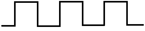
In this project, we will show how to build a square wave generator circuit that allows for adjustable frequency and amplitude of the output square wave signal.
This square wave generator circuit can be built simply a 555 timer chip and a few resistors, capacitors, and potentiometers.
The circuit is very basic. It simply uses one chip, a 555 timer.
A 555 timer is a very versatile chip. It can easily create square waves when in astable mode of operation. This circuit utilizes that principle, that 555 timers can easily generate square wave signals.
The potentiometers allow us to vary the frequency of the output signal as well as the amplitude.
This circuit can function well simply if you need square waves or if you need to use it for an IC that requires clock pulses.
So below we'll explain in detail how to build this circuit as well as how it operates.
Components Needed
- 555 Timer Chip
- 200Ω potentiometer
- 1MΩ potentiometer
- 39KΩ resistor
- 1nF ceramic capacitor
- 100nF ceramic capacitor
The 555 timer can be obtained very cheaply from pretty much any electronic retailer.
The 555 timer can be obtained very cheaply from pretty much any electronic retailer.
The 555 timer is an 8-pin chip.
The pinout of the 555 timer is shown below.
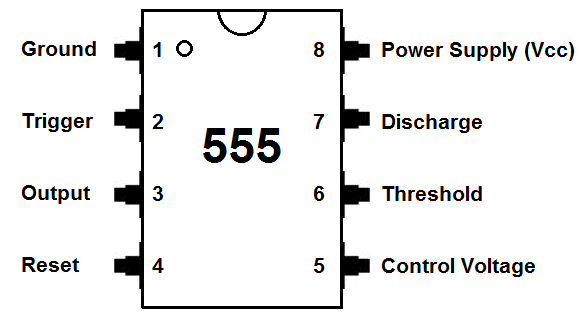
The 555 timer requires a power supply voltage of 4.5-16V. We connect this voltage to the VCC pin, pin 8, and we connect GND, pin 1, to ground.
The only other pins we use are the trigger pin, the output pin, the reset pin, and the threshold pin.
Pin 2 is the trigger pin. It works like a starter pistol to start the 555 timer running. The trigger is an active low trigger, which means that the timer starts when voltage on pin 2 drops to below 1/3 of the supply voltage. When the 555 is triggered via pin 2, the ouptut on pin 3 goes high.
Pin 3 is the output pin. 555 timer's output is digital in nature. It is either high or low. The output is either low, which is very close to 0V, or high, which is close to the supply voltage that's placed on pin 8. The output pin is where you would connect the load that you want the 555 timer to power. This may be an LED, for instance.
Pin 4 is the reset pin. This pin can be used to restart the 555 timer's timing operation. This is an active low input, just like the trigger input. Thus, pin 4 must be connected to the supply voltage of the 555 timer to operate. If it is momentarily grounded, the 555 timer's operation is interrupted and won't start again until it's triggered again via pin 2.
Pin 6 is the threshold pin. The purpose of this pin is to monitor the voltage across the capacitor that's discharged by pin 7.
When this voltage reaches 2/3 of the supply voltage
(VCC), the timing cycle ends, and the output on pin 3 goes low.
Adjustable Square Wave Generator Circuit Built with a 555 Timer
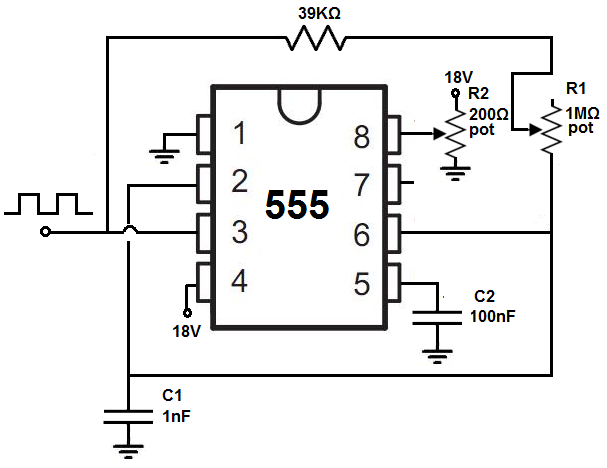
The adjustable square wave generator circuit we will build with a 555 timer chip is shown below.
The breadboard circuit of the circuit above is shown below.
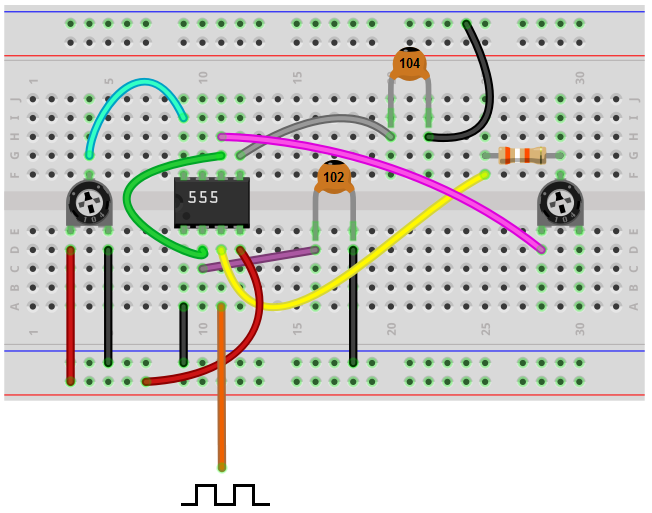
So this is our adjustable square wave generator circuit shown above.
So the first thing of concern for this circuit is power- what power the circuit will run off from.
Being that we are using a 555 timer chip, the maximum voltage that a 555 timer can withstand is 18V. Therefore, we use 18V for the supply DC voltage for this circuit. By attaching a potentiometer to the 18V, we create an adjustable power source, so that we can alter the amplitude of the output signal. If the potentiometer is turned so that it is offering full resistance, the voltage fed to the 555 timer is about 18V. This gives the maximum amplitude that the output signal can be. If we lower the resistance of the potentiometer, the voltage fed to the 555 timer decreases. This decreases the amplitude of the output signal.
For this circuit, we use a 200Ω potentiometer to allow for amplitude adjustment. You don't want to use a smaller potentiometer than this such a00s a 100Ω potentiometer, because most aren't rated to handle the amount of current that using a potentiometer this low will be. For example, with a 100Ω potentiometer, current will be 18V/100Ω= 180mA. Many potentiometers can't handle such high current and will burn out. 200Ω is a much safer bet lowering the current to 90mA (18V/200Ω). You can only use a 500Ω potentiometer. But it's best not to go higher than 500Ω. If you use a very large potentiometer value, amplitude adjustment will not work properly. Using low-ohm potentiometers allows for small changes to resistances, so that the amplitude changes slowly. Using large-ohm resistors causes abrupt changes to the amplitude, not giving good amplitude adjustment. If you use a 100KΩ potentiometer, for instance, slightly adjusting the potentiometer leads to abrupt changes in amplitude, which makes for poor amplitude adjustment.
This voltage is fed into the V+ pin of the 555 timer, which is pin 8.
So again, if the potentiometer is offering full resistance, the amplitude is at its maximum amplitude. As we lower the resistance of the potentiometer, the amplitude decreases and decreases until the voltage feeding into pin 8 is so low, that no signal is output.
18V is, fed into pin 4 of the 555 timer. Pin 4 is the reset pin of the 555 timer. This pin is active low, which means it is triggered when fed a voltage near ground or 0V. Therefore, this pin must remain connected to a positive voltage source in order for the circuit to work.
So, this fulfills the power for the circuit.
Now we get more into the other facets of the circuit.
Besides the amplitude, which we have covered, we now get into the frequency aspect of the circuit, how the frequency of the signal. And the frequency of the output is determined by the potentiometer R1 and capacitor C1. These form an RC network that determine the frequency of the output signal. The product of RC is equal to the time period of the output signal. By decreasing the value of the resistor, we decrease the time period, which creates a signal with a higher frequency. By increasing the value of the resistor, we increase the time period, which creates a signal with a lower frequency. The potentiometer allows us to change the frequency by changing the value of the RC network.
The value of the capacitor C1 that we have chosen is 1nF. If you want even a greater frequency that can go lower, you cna choose a lower value capacitor such as in the picofarads range. This extends the frequency range of the circuit, at the high end. The smaller of a capacitor you use, the higher the frequency. For example, a 330pF capacitor causes even a faster frequency.
The potentiometer value that we use for the RC network is a 1MΩ potentiometer. You can also use a 10MΩ potentiometer if you want to extend the frequency range of the circuit, at the low end. The greater of a resistance value you use, the lower frequency can extend. For example, with a 10MΩ potentiometer, the frequency will be just a few hertz on the lower end of the frequency range when the potentiometer is offering its full resistance.
The 555 timer is a very good chip that is able to produce and output very good, high-quality square wave signals. And depending on the values you use, you should be able to get any square wave of any frequency you desire. The 555 timer chip does have a ceiling of frequency but it is several megahertz. So until you exceed this, the circuit should be able to do what you want it to accomplish.
So this is an adjustable square wave generator circuit.
To see how this circuit operates in real life, see the video below.
Related Resources
How to Build a Precision Peak Detector Circuit
How to Build a Peak-to-Peak Detector Circuit