
How to Build a Peak-to-Peak Detector Circuit
In this project, we will show how to build a peak-to-peak voltage detector circuit.
This is a circuit that measures the amplitude of the peak-to-peak voltage of a signal.
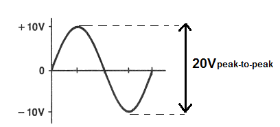
The peak-to-peak voltage is the voltage all the way from the tip of the negative portion of a signal to the tip of the positive portion of a signal.
For example, if an AC signal goes to +10V on its positive cycle and to -10V on its negative cycle, it has a peak-to-peak voltage of 20V. The peak voltage of this signal, however, is 10V. Because the peak voltage only takes into account the top of the positive half cycle.
So, if an AC signal swings halfway from the 0V line, the peak-to-peak voltage will always be double the peak voltage of the signal.
The circuit that we're building here takes an AC signal that swings from the 0V, equally positive and negative during their respective cycles and clamps it so that the negative peak of the AC signal is at the 0V line. Now the signal swings from 2 times the peak voltage to the 0V line. A capacitor at the end of the circuit then charges up to this maximum voltage, which represents the peak-to-peak voltage. Therefore, the voltage across the capacitor represents 2 times the peak voltage, which is the peak-to-peak voltage.
The voltage across a capacitor is DC voltage. Therefore, even though, we're using an AC voltage source as the input voltage source, the output voltage is a DC voltage. So, this circuit is an AC-to-DC converter. But that's not the point. The circuit achieves its goal of measuring the peak-to-peak voltage of an AC signal. It's able to give out the peak-to-peak amplitude, so that we know the maximum voltage that a signal reaches when considering it from an aspect of being peak-to-peak.
We will show how to build this peak-to-peak voltage detector circuit below.
Components Needed
- 2 100µF electrolytic capacitors
- 2 1N4001 Diodes
All we need to build this circuit are 2 diodes and 2 capacitors.
The diodes can be any really. Any diode from the popular and widely used 1N400X family will work with this circuit.
The capacitors used in this circuit are electrolytic capacitors. 100µF will work fine.
Peak-to-Peak Detector Circuit
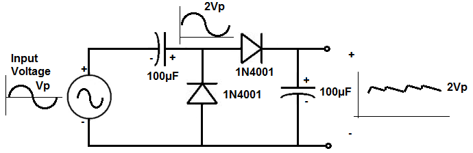
The peak-to-peak voltage detector circuit we will build with 2 diodes and 2 capacitors is shown below.
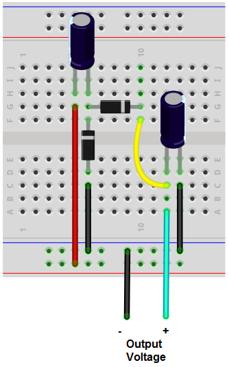
The breadboard circuit of the circuit above is shown below.
So input into this circuit is an AC voltage signal.
This circuit works by the fact that it is a DC clamper and a peak detector cascaded together. If you cascade these two together, you get a peak-to-peak voltage detector.
The input AC signal is positively clamped. So instead of an AC signal swinging positive and negative from the 0V line, it is clamped to being all above the 0V line. Therefore, the maximum value is now 2 times the peak voltage, since the circuit is shifted up. This is clamping part of the circuit.
The next part of this circuit features the last capacitor. The full clamped signal now enters into the capacitor. A capacitor stores voltage up to the maximum voltage that the signal is. So if the peak-to-peak voltage is 20V, the capacitor stores a DC voltage equivalent to 20V. Just make sure that the capacitor has a voltage rating above the maximum voltage you are using so that it doesn't damage the capacitor. So if you're expecting a voltage range to say 20V, for example, make sure to use a capacitor that has a voltage above 20V, such as at least 25V.
After this, to check the voltage across the capacitor, all you need to use is a DC voltmeter to read the peak-to-peak voltage value.
Realize for this circuit that the displayed peak-to-peak voltage on a DC voltmeter will be slightly lower than the true peak-to-peak value. This is because you must take into account the voltage drop that occurs across the diode. Usually silicion diodes consume about 0.6-0.7V, while germanium diodes consume about 0.3V. Therefore, the output voltage will be lowered by this amount.
Also for this circuit, realize that the discharge time have the capacitor and the load of the circuit must be much greater than the period of the incoming signal. This is so that the voltage across the capacitor doesn't discharge quickly, losing the peak-to-peak voltage value. If this is met, in this circuit, you get good clamping action and good peak-to-peak detection. The output ripple will be small.
This circuit has application when using an AC voltmeter may get the wrong reading. For instance, suppose an AC signal swings from +40 to -10V. If you try to measure this with an ordinary AC voltmeter, you will get an incorrect reading.
If you use this peak-to-peak detector circuit built, you will read 50V for the peak-to-peak value.
Related Resources
How to Build a Square-to-Sine Wave Converter Circuit
How to Build a Sine Wave Generator Ciruit with a Single Transistor
How to Build a Sine Wave Generator Circuit with a 555 Timer
How to Build a Triangle Wave Generator Circuit with a 555 Timer
How to Build a Clock Circuit with a 555 timer
How to Build an Astable Multivibrator Circuit with Transistors
How to Build a Multivibrator Circuit with a 4047 chip (for astable mode operation)
How to Build a Voltage-Controlled Oscillator Circuit with a 4046 Chip
How to Build an Oscillator Circuit with a 7414 Schmitt Trigger Inverter Chip
How to Build a Ramp Generator with Transistors
How to Build a Voltage-controlled Oscillator with a 555 Timer Chip