
How to Build a Peak Precision Detector Circuit
In this project, we will show how to build a precision peak detector circuit.
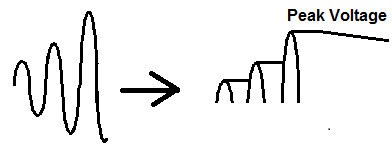
This is a peak detector circuit that can detect the peak of an input analog signal with more precision than a simple peak detector.
Previously, we've shown how to build a peak detector circuit using only the simple components of a diode and a capacitor. Though this circuit is effective and works well, it is only good for rough estimates and lacks high precision. This is because simple components are much less sophisticated than more complex components such as integrated circuits and are subject to leakage and a number of other factors that make it lack precision. Diodes will allow some reverse leakage current. Capacitors will leak small amounts of current over time. Even those these are small, over time, they continue and equal to substantial loss. All these factors contribute to making a low-precision peak detector that should not be used in cases of high-precision needs.
So instead of using only simple components to build a peak detector circuit, we also add buffers to the circuit. The buffer is much more stable than a diode. A diode is a simple component that is not as precise. Understanding, the physics a diode is basically a PN junction semiconductor material and it is very sensitive to temperature variation. The reverse current is very sensitive to the junction temperature. If you're building this circuit at home, where you're at room temperature and you keep it there, you shouldn't encounter too any problems because of this. But if you're building a commercial-grade product, you wouldn't want to be use a diode for precision applications due to fluctations the diode can cause. Instead an op amp provides much better stability with a diode rather than with just a diode alone.
So we will still use a diode in our circuit but not alone. The diode is still important because the diode will be reverse biased to the capacitor, so that the capacitor cannot discharge back. We want the capacitor to hold the charge once it gets stored up. This way, we are able to hold the peak value. But we will use a buffer with the diode. The buffer acts a voltage follower because it follows the input voltage.
So we will show how to design this precision peak detector and what factors need to be taken into consideration when
choosing the components.
Components Needed
- 2 LM741 Op Amp Chips
- Diode
- 100nF electrolytic capacitor
The LM741 is an operational amplifier chip.
It is composed of a single op amp.
The LM741 is an 8-pin chip.
The pinout for the chip is shown below.
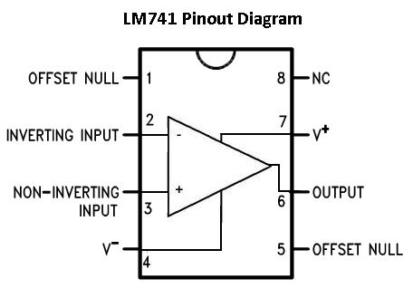
Pin 1: Offset Null- This pin will be left open
Pin 2: Inverting Input- This is where the positive part of the input signal that we want to
amplify goes if we want our amplified signal inverted. If we don't want it inverted, we place the positve
part of the signal into the Non-inverting terminal and place the negative or ground part of our signal
here.
Pin 3: Non-inverting Input- This is where the positive part of the input signal that we want
amplified goes if we want our signal non-inverted.
Pin 4: V-- The LM741 Op amp is a dual power supply op amp, meaning it must be supplied positive
DC voltage and negative DC voltage. Pin 4 is where the op amp gets supplied with negative DC voltage.
Pin 5: Offset Null- This pin will be left open.
Pin 6: Output- This is the terminal where the output, the amplified signal, comes out of. Whatever
output the amplifier will drive gets connected to this terminal.
Pin 7: V+- This is the terminal which receives the positive DC voltage.
Pin 8: NC- This pin will be left open.
Precision Peak Detector Circuit
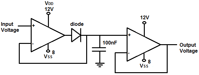
The precision peak detector circuit we will build with 2 LM741 chips is shown below.
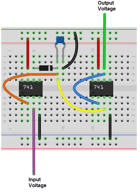
The breadboard circuit of the circuit above is shown below.
So for this circuit, to power the LM741 chip, we place about 12V into VDD, pin 7, and we ground pin 4, the ground pin. This establishes sufficient power for the chip.
The input to the first buffer is pin 3. To the input, we can the input voltage which we want to buffer.
The output of the buffer is pin 2. To the output, we place a diode in series and then a capacitor in parallel.
We then connect the anode of the capacitor to a second buffer. The second buffer's input is pin 5. The output of the second buffer is pin 4. The output from the second buffer is the output of the circuit and represents the original input voltage signal.
How this circuit works is the buffer acts as a voltage follower.
A buffer, in general, follows the voltage exactly. When we place a diode in series with the output of the buffer, the voltage stored up in the capacitor cannot discharge back through the diode because to the capacitor, the diode is reversed biased. So once the capacitor gets charged up to the peak voltage of the input signal, it cannot discharge back either through the diode (since it is reverse biased) or the input of the second buffer (since it has such high input impedance). The high input impedance of the buffer impedes the leakage of current from the diode. Since current, I=V/R, where R is the resistance, this high resistance value impedes the flow of current from the diode. Thus, the current is contained across the the capacitor.
If we didn't have this second buffer and we connected the output of the capacitor directly to the output load, it would be much more susceptible to leakage. The high input impedance from the buffer prevents current from flowing out of the capacitor and contains it within the capacitor. This allows the peak of the voltage to remain relatively constant, with a very slow drop of the voltage due to leakage. Even with high input impedance, there will always be some droop because the resistance isn't perfectly infinite. So very small amounts of current will still leak and the voltage will droop down still, though not much.
This is why we use 2 buffers.
Now that you know conceptually how this circuit works, we'll now go into some of the considerations you have to when when choosing the value of the components, chiefly the capacitor.
The diode can really be any diode. It isn't very important.
What's really important is the values of the capacitor we choose. When choosing the capacitor, we have to consider both the capacitance and voltage rating.
The voltage rating is simply how much voltage we expect the circuit will peak at. We want the capacitor to have a voltage rating higher than the peak voltage of the input signal. Therefore, if we expect your peak voltage to be 9V, you should use a higher voltage-rated capacitor such as 12V or 15V or higher.
The other value we must take into consideration is the capacitance of the capacitor. This is important because it works hand in hand with the slew rate of the capacitor. If you choose a capacitance value that is too small, you risk having the capacitor have a fast droop rate. This is because with a smaller reactance, the RC network has a smaller value, and thus discharges faster. If you choose a capacitance value that is too large, the slew rate of the capacitor may not be quick enough to charge up the capacitor. This is because the RC network now has a greater time charge time. If the slew rate isn't fast enough to match this capacitance value, there may be huge delay between the input and output signals, so the circuit will be slow and efficient. So you want to keep the capacitor as small as possible for maximum speed and efficiency (smaller capacitors take less time to charge) but you also want to have the capacitor large enough so that you don't have a lot of droop (smaller capacitors discharge quicker). So it's a delicate balancing act.
Another thing that is very important is the type of capacitor that is used. Capacitors have a phenomenon called the dielectric absorption. This is when capacitors have a memory, so to say, in which even after being fully discharged, they can rise back to their previous memory state. This is a real problem when you're talking about a precise peak detector circuit. We do not want the capacitor having these memory and rising back to previous states. This could really mess up the functionality of a precision detector. The type of dielectric material used in the capacitor determines its dielectric absorption. We want to use a capacitor with a low dielectric absorption such as a polystyrene capacitor or, even better, a teflon-based capacitor. So if you want to occasionally short out the capacitor, completely discharging it, having a low dielectric absorption capacitor is very important.
So, for our circuit, we use a 100nF polystyrene or teflon-based capacitor. This value and type of capacitors suits this circuit well.
An important consideration that must be kept in mind is the frequency of the input AC signal. Keeping in mind that the op amp has a certain slew rate, in which it can amplify voltage per unit time, the op amp will only be able to properly amplify signals up to a certain frequency. Above this threshold, the slew rate of the op amp will cause poorly formed and distorted waveforms on the output.
The LM741 has a slew rate 0.7V/μs. This means that it can output a voltage of 0.7V for every microsecond of time that transpires. We'll do the math in reverse so that you can see the frequency the op amp is capable of managing. This all depends on the amount of voltage that it outputs. So being that the slew rate is specified in terms per each microsecond, let's do the math. The inverse of a time period is the frequency. F= 1/t, where T is the time period. So, F=1/T= 1/1μs= 1MHz. So the op amp is capable of outputting 0.7V for a 1MHz signal. But 0.7V is a small voltage to output. Many times, the voltage needed on the output will be much higher. Let's say, the op amp will pass 10V on the output. If you take 10V and divide it by 0.7V, you get 10V/0.7V= 14.3. So 10V is 14.3 times the voltage of 0.7V. So we said that the LM741 can output 0.7V per 1MHz. Since 10V is 14.3 times the voltage of 0.7V, this means that the op amp can output 10V per 69930Hz (1MHz/14.3=69930Hz). Any frequency above this for 10V will be greatly distorted due to limitations of the slew rate. So you can see for this circuit if we're outputting 10V, the frequency must be limited to about 60KHz, to be on the safe range. If you're outputting even a larger voltage such as 15V, the frequency limitation of the input voltage is 46729Hz (1MHz/21.4=46729Hz). To be on the safe side, it's good to limit the input voltage to a frequency a good distance away from the upper limit. This is because an op amp also has a minimum slew rate range. So the typical range for the LM741 is 0.7V/μs, while the minimum range is 0.3V/μs. So it's best to keep the upper limit at the minimum range to have the highest quality output signal.
But seeing how the slew rate calculations work out and how it puts a limitation on high-frequency signals is important to get how signal integrity for this circuit. For this circuit, the minimum slew rate range calculates to be approximately 30KHz. So the input voltage signal should go no higher than 30KHz or distortion may be introduced into the output signal.
The LM741's slew rate of 0.7V/μs isn't particularly fast. If you are dealing with relatiely low frequency applications such as 20KHz or less, it will work fine enough, because the slew rate can still output voltage at a fast enough rate. However, if you are dealing with frequencies over 50KHz or so, it's best to use a high-speed op amp. A high speed op amp has a much greater slew rate, so it's able to output voltage at a greater rate than a regular op amp. A high-speed op amp typically has a slew rate of 100V/μs. The LH0063C is a high-speed op amp that has a slew rate of up to 6000V/μs, so if you are using an op amp to deal with high to very high frequencies, you would need op amps with high slew rates. But for basic low-frequency applications, op amps such as the LM741 are perfectly fine.
Another limitation of this circuit is the input voltage of the LM741. So the LM741 can't accept an infinite voltage range. It can only accept voltages up to values its rated for. So you have to also keep this in mind.
But this circuit works very well as a precision-type peak detector circuit. It's much more stable than simply using simple components to control due to greater temperature
stability and impedance factors.
Related Resources
How to Build a Peak-to-Peak Detector Circuit