Arduino LED Flasher Circuit
In this project, we will go over how to build an arduino LED flasher circuit.
We will use a standard arduino board, doesn't matter which, and connect it so that it flashes an LED a certain amounts of times on and off repeatedly to create an LED flasher circuit.
An arduino is a self-contained microcontroller. Therefore, it can be programmed via the language Processing to turn the LED on for a certain period of time and turn it off for a certain period of time- over and over. To control the amount of time the LED will be on and the amount of time it will be off can easily be decided by our software code.
Once the arduino board is connected to a computer via USB, it has 5V of power. It gets power via the USB. The LED is then connected to its digital output pin. All we must then do is write our program which flashes the LED on and off.
Components Needed
- Arduino Board
- LED
- USB Connector
The arduino board can be any of several. It can be an arduino uno, duemilanove, etc.
The 5 volts of power, again, comes from the USB connection from the arduino board to the computer.
The USB connector that needs to be used is one which has a USB type A connector on one side and a Type B connector on the other.
Arduino LED Flasher Circuit
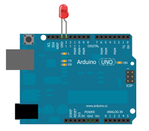
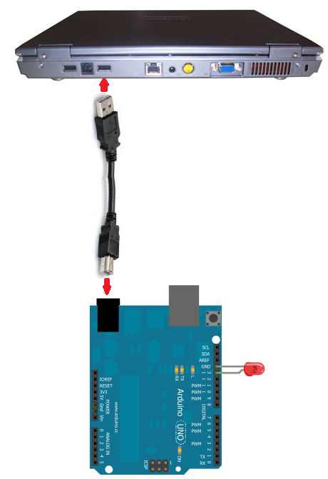
To build this circuit, we simply connect the anode of the LED (the longer of the 2 ends) to digital pin 13 of the arduino board and the cathode of the LED to the ground Pin of the arduino board.
The circuit connected will look like this:
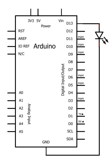
The schematic diagram for this circuit is:
Once the circuit is connected in this way, all we have to do is take the USB connector and plug the type A
connector into the computer and the type B connector into the arduino board.
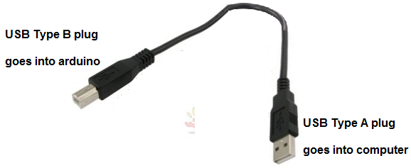
The USB type A connector goes into the computer which will program the arduino and the USB type B connector goes into the arduino board. Now the arduino has direct connection to the computer and can be programmed. Arduinos are programmed via USB connections.
The last stage now is to write and then run the code which will make the LED connected to the board flash on and off.
Arduino LED Flasher Code
The code needed to flash the LED on the arduino board is shown below.
It is written in the processing language and ran through USB connection.
const int LED= 13;
void setup()
{
pinMode(LED, OUTPUT);
}
void loop()
{
digitalWrite(LED,HIGH);
delay(1000);
digitalWrite(LED,LOW);
delay(1000);
}
This code above turns the LED on and off. It turns the LED on, waits a second, then turns the LED off, and waits a second. Therefore, the LED blinks or flashes
every second. The 1000 value is specified in milliseconds (ms). Since 1000 milliseconds equals 1 second, this is the commands that the arduino follows. You can adjust
this value to suit your needs. If you want the LED to flash quicker or more frequently, then you would decreased the delay() value. If you want the LED to flash
slower, then you would increase the delay() value.
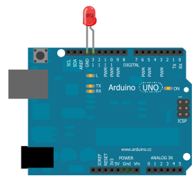
Below is the actual real-life circuit of this project built so that you can see how the LED flashes on the arduino board.
Related Resources
How to Drive a 7 Segment LED Display with an Arduno
How to Connect and Read a Keypad with an Arduino
How to Display Text on an HD44780 LCD Using an Arduino
How to Build a USB-powered Device
How to Build a DC Motor Circuit
How to Build a Speaker Circuit with Adjustable Volume
How to Build a Simple Microphone circuit
How to Build a Touch Sensor Circuit