
How to Display Text on an HD44780 LCD with an Arduino
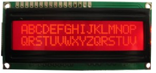
In this article, we will go over how to connect an HD44780 LCD to an arduino in order to display any text that we want to show on the LCD.
To do this, first, we must make the appropriate physical connections from the arduino board to the LCD. Then after, we must write the code so that whatever text we want displayed comes up on the LCD.
LCDs are pretty much the standard now in order to display text to users of a device. Almost all electronic devices which give a readout to users of some type of data use LCDs to do so. This includes CD players, microwaves, thermostats, ovens, all come with LCDs which display some type of readout so that users can obtain some type of data. For thermostats, it's the temperature. For microwaves, it's a how much time until it shuts off. For CD players, it's what track in the CD is currently playing. LCDs are so important in electronics today that learning as much about them is a smart way to keep yourself up with the industry.
So in our project, learning how to write text to LCDs is a great way to eventually learning how to build electronic devices that can display data out to an LCD so that a consumer can obtain the data he or she needs.
LCDs are also inexpensive. So when creating products with LCDs, the LCDs do not significantly mark up the price of the product.
There are plain text LCDs and graphical LCDs (GLCDs). Graphical LCDs can display fine graphical detail better than text. They are avaiable for a small
price premium over text displays.
Components Needed
- Arduino Board
- HD44780 LCD
- 10KΩ potentiometer
- USB with Type A and Type B Connectors
- Computer
We need a computer to write the code needed to send the text we want to display on the LCD to the arduino board. The arduino board then transfers this data to the LCD.
We need a USB with a type A connector and a type B connector. The type A connector connects into the computer and the type B into the arduino board. Thus,
we have a connection between the arduino and the computer, so that we write the code on the computer and then upload it to the arduino.
The Wiring
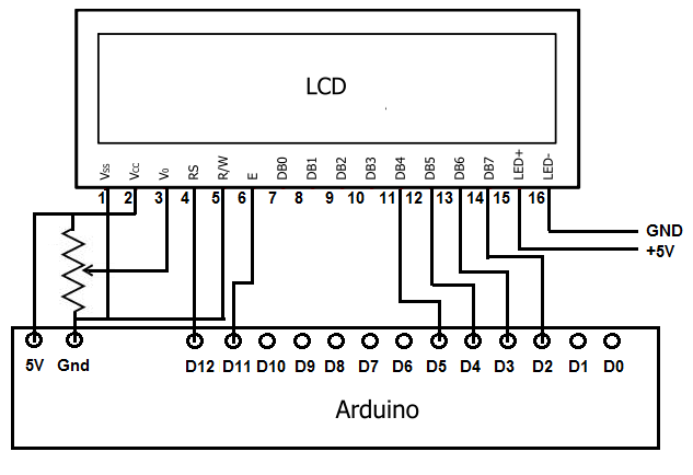
To wire up the HD44780 LCD to the arduino, we wire it according to the diagram below:
For a written version of all the physical connections which you see above, we created the table below:
LCD
Pin
Function
of LCD Pin
Arduino
Pin
1
Gnd
Gnd
2
+5V
5V
3
Contrast
NOT
CONNECTED
4
RS
(Register Select Pin)
12
5
R/W
(Read/Write Pin)
Gnd
6
E
(Clock Enable Pin)
11
7
D0
NOT
CONNECTED
8
D1
NOT
CONNECTED
9
D2
NOT
CONNECTED
10
D3
NOT
CONNECTED
11
D4
5
12
D5
4
13
D6
3
14
D7
2
15
Anode
(for backlight)
5V
16
Cathode
(for backlight)
Gnd
For a more in-depth explanation of the pinout connections to the LCD, see HD44780 LCD Pinout. This will help to explain the pins, and what each does, of the LCD.
Basically, pins 1 and 2 give power to the LCD. This is why they connected to the 5V pin and the ground pin of the arduino. Without power, the LCD cannot power up and, thus, display anything.
Pin 3 gives contrast to the LCD screen. It normally hooks up to a 10KΩ potentiometer to pin 3 of the LCD. The wiper terminal (variable portion of the potentiometer) is what hooks up to pin 3. The 2 end terminals of the potentiometer connect to the 5V and ground terminals of the arduino. It doesn't matter which ends connect to each. One end just has to connect to 5V and the other end connects to ground. By adjusting potentiometer with this setup, we can adjust the contrast of the LCD screen. If this pin is not adjusted properly, a user may see no output at all. So adjusting this until text can be seen if all other connections are made is crucial to the functioning of the LCD.
Pin 4 is the register select pin. This register select pin can be in 1 of 2 modes. If no voltage is given to it (it is LOW), then it is in command mode. If voltage is given to it (it is HIGH), it is in data mode. We connect this pin to the arduino's (digital) D12 pin.
Pin 5 is the R/W, or read/write, pin. This pin, just like the previous one, can be in 1 of 2 modes. If no voltage is given to it (it is LOW), then it is in write mode. If voltage is given to it (it is HIGH), then it is in read mode. If it is in write mode, then we can write text to it so that it can be displayed. When it is in read mode, this is only necessary in rare instances when we want to read what the LCD is displaying. The majority of the time, though, it will be connected in write mode. For simplicity sake, we will only be writing to the LCD, so we will have it permanently connected so that it stays in write mode. To do this, we connect it to the ground pin of the arduino. Again, this makes it permanently be in write mode. If you want to be able to change it from read to write mode and vice versa, you would connect this to a digital pin.
Pin 6 of the LCD is clock enable pin. The HD44780 LCD is an LCD which is run by a clock. It is falling edge triggered so it executes all instructions it receives on the falling edge of each clock cycle. In order for the LCD to process instructions, the clock must be enabled, so this pin must be connected. We connect this pin to arduino digital pin D11.
Pins 7, 8, 9, 10 of the LCD are left unconnected. The HD44780 LCD can run on 1 of 2 modes- 4 bit mode or 8 bit mode. We will use 4 bit mode. When using 4 bit mode, we only have to use 4 digital pins of the LCD. When using 8 bit mode, we have to use 8 digital pins of the LCD. There is a theoretical advantage to using 8 bit mode in terms of the LCD efficiency, but not enough to warrant 4 more connections. This is why we use 4 bit mode and leaves pins 7, 8, 9, 10 open.
Pins 11, 12, 13, 14 are the 4 digital pins of the LCD. These are the digital pins that represent the 4 bits of 4-bit mode. These represent the digital bits of the actual data that we transfer to the LCD. So, for example, when we send text to the LCD so that it's displayed, these pins transfer that data to the LCD. Pins 11, 12, 13, 14 connect to the arduino board pins D5, D4, D3, D2, respectively.
Pins 15 and 16 represents the backlights of the LCD. This is an optional connection. If you want the backlights to be on, then you must power them. Pin 15 is the anode pin. This pin receives the +5V of positive voltage which the LED needs. Pin 16 represents the ground pin.
This represents all the wiring that must be done from the arduino board to the LCD. Now all we have to do is write
the code (instructions) that the LCD needs to display the text we want it to.
Code to Send Text to a HD44780 LCD
#include <LiquidCrystal.h>
//In my example, I use a 20x4 LCD, thus it has 4 rows and 20 columns
//If you use another LCD, type in the appropriate rows and columns below
const int numRows= 4;
const int numCols= 20;
LiquidCrystal lcd(12, 11, 5, 4, 3, 2);
void setup()
{
lcd.begin(numCols, numRows);
lcd.print("Hello there");
}
void loop()
{
lcd.setCursor(0,1);
delay(1000);
lcd.print(millis()/1000);
lcd.print(" seconds elapsed");
}
So this is the code to send and display text to the LCD.
In our example, we display the text, "Hello there" on our LCD, followed by the number of seconds that has elapsed once the code is uploaded. You can change this to whatever text you want shown. Customize to it anything or you can run our code, as is.
We will now go over the code.
The first line includes the LiquidCrystal library so that we can use its prebuilt code functions.
The second block code declares the number of rows and columns that the LCD that we use has. There are many different types of LCDs, including 16x2 20x4, etc. Here we declare the rows and columns which the LCD has.
The third line of coe declares all the digital pins of the arduino board we will be using. On our arduino board, we use its digital pins D12, D11, D5, D4, D3, and D2. These we all declare.
The third block of code, the setup() function, instructs the LCD where to begin and what text to print.
The fourth block of code, the loop() function, sets the cursor (or blinker) at column 0, line 1.
This is the place on the LCD where we want the cursor
to blink on and off from.
And this is how we display text on a HD44780 LCD using an arduino.
See the video below to see this circuit in action. It displays the message "Hello there" followed by the number of seconds
that has elapsed since the software has been uploaded to the board.
Related Resources
How to Drive a 7 Segment LED Display with an Arduno
How to Connect and Read a Keypad with an Arduino
How to Build a Motion Detector Circuit with an Arduino
How to Build a Motion Sensor Light Circuit with an Arduino
How to Build a Hall Effect Sensor Circuit
How to Build a Motion Detector Circuit
How to Build a Vibration Detector Circuit