How to Build an RGB LED Circuit with an Arduino
In this project, we are going to build and operate an RGB LED circuit using an arduino microcontroller.
An RGB LED is an LED that can light up either red, green, or blue.
The type of RGB LED we will use in this circuit is the more common cathode RGB LED. This is an LED in which all the grounds of the LEDs are tied together common. So then we just have to connect each of the anodes to sufficient positive voltage to turn them on.
Using a microcontroller such as the arduino, we can control what LED(s) turn on at any given time and for how long.
The RGB LED is a dynamic LED because of the fact that it can light up to many different colors. Therefore, if you need multiple colors to be shown and if you have very limited space on a board (where you can't fit 3 separate LEDs), an RGB LED works perfectly.
In this circuit, we will use toggle switches to control the RGB LED. We can turn on one toggle switch at a time, 2 at a time, or all 3 at a time. If we turn on one, only that color will light up. If we turn on multiple LEDs, all the selected LEDs will turn on. Depending on which pin we draw HIGH determines LED turns on.
And we draw pins HIGH or LOW in our software code to switch LEDs on and off.
In this circuit, we will create a looping pattern. First, we will turn on the red LED for 3 seconds. Then we will turn that off and turn the green LED on for 3 seconds. Then we will turn that off and turn on the blue LED for 3 seconds. Then we will loop back and turn on the red LED.
This circuit is just for demonstration purposes so that you can see how an RGB LED works.
Components
- Common cathode RGB LED
- 3 220Ω resistors
- Arduino
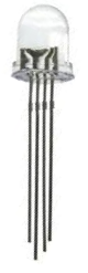
The RGB LED is a 4-pin LED.
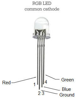
For the common cathode RBG LED, one pin is ground (pin 2) and the other 3 pins are the anodes of the red, green, and blue LED.
The pinout of the common cathode RGB LED is shown below.
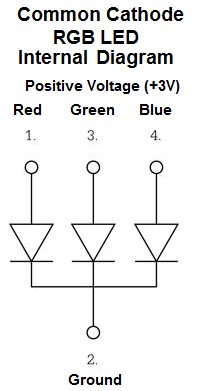
The RGB LED we are using is a common cathode LED. This means that all the grounds of the LED are tied together, i.e. they are common. We have to connect all of the anodes of the LEDs to sufficient positive voltage, which in this case is 3V.
The diagram at the following link shows the internal layout of the RGB LED:
Internal Diagram of a Common Cathode RGB.
So with common cathode RGB LEDs, we connect pin 2 to ground. This grounds all of the LED grounds. And then we connect all of the toggle
switches to positive voltage and ground, so that we can turn off or on whichever LED.
Arduino RGB LED Circuit
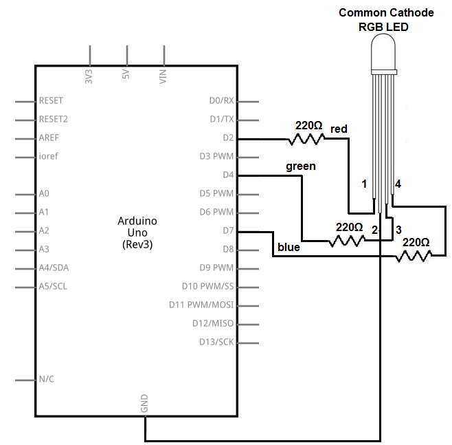
The RGB LED circuit we will build to be controlled with an arduino microcontroller is shown below.
This above circuit built on a breadboard is shown below.
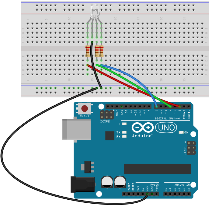
The connections are pretty simple.
We connect the ground pin (pin 2) of the RGB LED to the ground terminal of the arduino. This grounds all of the LEDs pins.
We then connect the anodes of each of the LEDs to digital pins on the arduino microcontroller through 220Ω resistors. These resistors are there to limit current to the LED so that it doesn't receive excess power and burn out.
The digital connections then can be complete the powering to the LED. When we pull the anode of an LED HIGH through our software code, we complete power to the circuit and the LED lights. Since all the LEDs are connected to ground through pin 2, all we need is sufficient voltage at the anode end to power on an LED. So in our code, to turn on an LED on, we just draw it to a HIGH state.
All the anodes of the LEDs are connected to digital pins on the arduino. This is because digital pins work perfectly with digital devices such as LEDs which can only be in 1 of 2 states: either on or off. Since LEDs can only be on or off, they are put on digital pins, which can either be HIGH (LED on) or LOW (LED off).
Analog pins on the arduino can also act as digital pins, but as to make it more straightfoward and avoid confusion, we just tie them to digital pins.
The anode of the red LED (pin 1 on the RGB LED) is connected to digital pin 2 on the arduino.
The anode of the green LED (pin 3 on the RGB LED) is connected to digital pin 4 on the arduino.
The anode of the blue LED (pin 4 on the RGB LED) is connected to digital pin 7 on the arduino.
Again, the anode drawn LOW on any of these anodes makes the LED be off. The anode drawn HIGH on any of these anodes makes the LED be on.
Multiple LEDs can be lit at the same time if multiple pins are drawn HIGH.
Now all we need is the code in order to run this circuit.
Code
The code needed to operate this RGB LED circuit so that it rotates between red, green, and blue in 3-second intervals with an arduino is
shown below.
const int redLED= 2;
const int greenLED= 4;
const int blueLED= 7;
void setup()
{
pinMode(redLED, OUTPUT);
pinMode(greenLED, OUTPUT);
pinMode(blueLED, OUTPUT);
}
void loop()
{
digitalWrite(redLED,HIGH);
delay(3000);
digitalWrite(redLED, LOW);
digitalWrite(greenLED,HIGH);
delay(3000);
digitalWrite(greenLED, LOW);
digitalWrite(blueLED, HIGH);
delay(3000);
digitalWrite(blueLED, LOW);
}
This code turns on the red LED first, then the green, then the blue. Each LED is on for 3 seconds at a time.
In the first block of code we describe the connections of the anode pins of the LEDs to the arduino board. The red LED anode is connected to digital pin 2, the green to digital pin 4, and the blue to digital pin 7.
We then declare all the LEDs as outputs. They're not inputs into the arduino board but outputs.
We then have our loop() function, which is the main loop that loops over and over and over again. In this code, we set it up so
that the red LED is drawn HIGH first for 3 seconds. We do this with the digitalWrite() function putting it HIGH, turning the LED on. We then use
the delay() function with 3000 as the value to delay 3000 milliseconds, which is 3 seconds. We then turn in the red LED with the digitalWrite() function
with the parameter LOW. We then do the same for green and the blue LEDs. After this, the function loops over turning the red LED again on. This continues
forever unless the program is halted.
And this is how a microcontroller such as the arduino can control an RGB LED.
An RGB LED is good for a variety of reasons. If you need multiple colors to be shown for a device such as to serve as indicator status and you have limited phyiscal on a board, an RGB LED can work very well. An example of this is like a printer or a fax machine or copy machine in which a green light means it's working, while a red light means it's not working and another color in between may mean it's in progress. So that's a purpose of an RGB LED. Another can be just to serve as a light show, kind of like what we've done here in this circuit.
Related Resources
How to Build a Common Cathode RGB LED Circuit
How to Build a Common Anode RGB LED Circuit