How to Build an Infrared Proximity Switch Circuit Using an Arduino
In this project, we will build an infrared proximity switch circuit using an arduino.
This is a circuit in which a switch activates when the infrared sensor detects an object in its proximity.
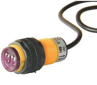
The infrared proximity switch sensor is a reflection-type photoelectric snesor which sends and receives infrared beams. Infrared proximity switches work by sending out beams of invisible infrared light. A photodetector on the proximity switch detects any reflections of this light. These reflections allow infrared proximity switches to determine whether there is an object nearby. When the infrared is able to read back the infrared beams that it sends out, then this means the path is of infrared is unimpeded, which means there is no object nearby. When the infrared sensor cannot read back the infrared beams it sends out, this means that the path is impeded and an object is nearby the sensor.
When an object blocks the sensor so that the sensor cannot read back the infrared beams, then the sensor will output a LOW signal on its signal line. The sensor's signal will normally be held HIGH when there is no object blocking its path. However, when an object blocks its path so that it cannot no longer read the infrared beams that it sends out, it outputs a LOW signal. A microcontroller board such as an arduino can easily detect and read this signal to determine if the sensor has sent a LOW signal, signaling it has detected an object.
This infrared sensor can tell us if an object is in the proximity of the sensor but cannot quantify how close or far the object is from the sensor. It simply functions to tell us if any object has been detected.
To test this circuit once it is built and with the program in place, all you have to do is place your hand or any object in front of the sensor.
In this circuit we are going to build, when the sensor is triggered, it will be made so that an LED turns on while an object is blocking and then shuts off when the object is removed.
An infrared proximity switch such as the one we are using in this circuit has great application for real life. The sensor can function to detect human beings. Being that the only moving objects in a building are humans, for the most part, the sensor circuit can be used to detect human intruders for a given area. And then once the sensor detects a person, the circuit can be made to do anything such as sound an alarm, flash sirens, have a buzzer alarm go off, have a camera begin recording, etc.
The sensor can also be made to pick up anything else that moves such as animals or any moving objects that may come into its path. So
the application in real life circuits is immense from this simple infrared proximity switch.
Components Needed
- Infrared Proximity Sensor Switch
- Arduino Board
- LED
The infrared proximity sensor switch can be obtained from ebay for about $5 normally.
It operates on 5V of power.
Being that an arduino has a 5V terminal, it is perfect for powering this sensor.
The distance the sensor can detect an object is between 3cm-80cm, and this distance is adjustable, so that if you want the sensor to only be triggered when within 10cm of the sensor, you can do so.
The infrared sensor is a 3-terminal device.
There is a red, green, and yellow wire.
The red wire is the +5V line. It connects to the 5V terminal of the arduino.
The green wire is the GND line. It connects to the GND terminal of the arduino.
The yellow wire is the signal line. It connects to a digital pin on the arduino to be read. Being that it only outputs 2 values, LOW or HIGH, it is a digital input. The arduino will either read it as LOW or HIGH. KNow that the signal on this sensor is active low. When the sensor does not detect any object, it outputs a HIGH signal. When it detects an object, it outputs a LOW signal (0v)
Infrared Proximity Switch Sensor Circuit
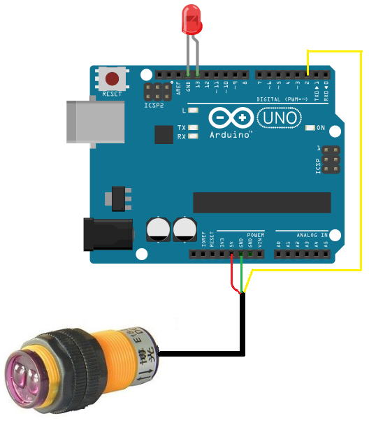
The schematic diagram of the infrared proximity switch circuit with an arduino is shown below.
This schematic diagram is as simple as it gets.
As explained, the sensor needs power so this is why the red wire gets connected to the 5V terminal and the green wire gets connected to the GND terminal. And the signal gets connected to digital pin 2. The digital pin can read this signal pin to determine whether it is HIGH (no object detected) or LOW (object detected).
The LED's anode is connected to digital pin 13 and the cathode is connected to GND.
Code
The code for the infrared proximity switch circuit is shown below.
int ledPin = 13;
int inputPin = 2;
int val = 0;
void setup()
{
pinMode(ledPin, OUTPUT);
pinMode(inputPin, INPUT);
}
void loop(){
val = digitalRead(inputPin);
if (val == HIGH) {
digitalWrite(ledPin, LOW);
} else {
digitalWrite(ledPin, HIGH);
}
}
We first initialize the pins we will be using. Since the LED is attached to digital pin 13 and the infrared sesnor is attached to digital pin 2, they are initialized to 13 and 2, respectively. We create a variable named val and initialize it to 0. This variable will hold the value of the signal pin of the infrared sensor, which will either be 1 (for HIGH) or 0 (for LOW).
In the setup() function, we set the LED as output and infrared sensor as input.
In our loop() function, which is the function which runs over and over repeatedly in an endless loop, we check the value of the signal pin. We execute the digitalRead() function to
read the signal pin of the infrared sensor. If the value is HIGH, this means that no object is detected and the LED will not light up. If the value is LOW, this means that an object has been
detected and the LED will light up.
And this is how an infrared proximity switch sensor circuit can work with an arduino.
Related Resources
How to Build a Light Detector Circuit with a NAND Gate Chip
How to Build a Night Light Circuit with a NAND Gate Chip
How to Build a NAND Gate Circuit Using a 4011 Chip