
How to Build an Astable Multivibrator Circuit with an LM741 Op Amp Chip
In this circuit, we will show how to build an astable multivibrator circuit using an LM741 op amp chip.
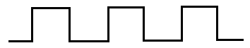
By definition, an astable circuit is that one that oscillates between 2 states, HIGH and LOW, over and over and over again, indefinitely. It never holds one state. It constantly cycles from HIGH to LOW, HIGH to LOW, repeatedly. Therefore, it produces a square waveform signal as output or closely resembles it in some way.
To differentiate, a bistable circuit is one that is any 1 of 2 states, indefinitely. It will hold this stable state. This means the circuit will either be LOW or HIGH. However, if a trigger pulse of the correct polarity and amplitude is applied to the circuit, it can switch states. An astable circuit, on the other hand, does not hold any stable state but constantly switches between the 2 states of HIGH and LOW. Therefore, it's able to switch on and off components at a rate determined by the values of the components that are chosen.
So this circuit functions as an astable multivibrator. It's constantly going from ON to OFF, ON to OFF, repeatedly. An astable multivibrator is a multivibrator which has no stable state, so it's constantly switching from ON to OFF, indefinitely.
In this circuit, we will flash on an output device, an LED, over and over again, so that it flashes on and off, on and off. This is the essence of astable multivibrator functioning.
This can be used for many types of circuits including any where you want a device flashing on and off, on and off. Flashing LEDs are used in many types of electronic devices, including in cars, dashboards, printers, fax machines.
It can be used basically for any circuit in which you want a device turning on and off at repeatable intervals.
We will show how to build this circuit below.
And we will show how we can modify the values of the capacitor and resistor to increase or decrease the flashing rate.
Components
- LM741 Op Amp Chip
- 1MΩ resistor
- 1µF electrolytic capacitor
- 2 1KΩ resistors
- LED
- 470Ω resistor
The LM741 is an general-purpose operational amplifier IC.
The LM741 is an 8-pin chip.
If you want to know all the pinout of the LM741 op amp, what each pin is and what each pin does, see s LM741 Op Amp Pinout.
As a quick runthrough, we will not be using pins 1, 5, and 8 on this chip.
Pin 2 is the inverting terminal and pin 3 is the noninverting terminal. These are the input terminals of the chip.
Pins 4 and 7 are the power pins of the LM741 in order to power it on. Pin 4 is V- and pin 7 is V+. We connect pin 7 to positive voltage and pin 4 to either ground or negative voltage. In this circuit, we connect it to negative voltage.
And, lastly, pin 6 is the output. This is the pin which the output sine wave
will come out of.
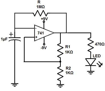
Astable Multivibrator Circuit with an LM741 Op Amp Chip
The astable multivibrator circuit we will build with an LM741 op amp chip is shown below.
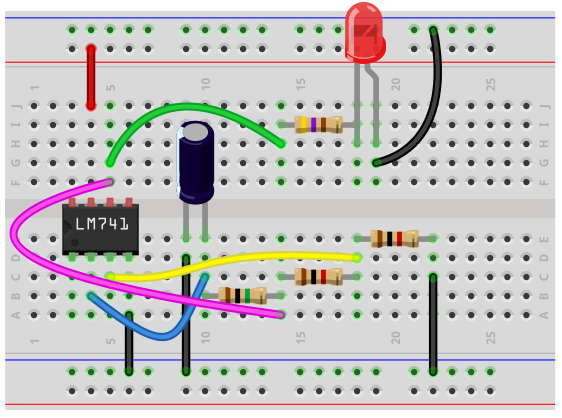
The breadboard circuit of the circuit above is shown below.
So the first thing that should be done is powering the chip. In order to power the LM741, we apply +0VDC to V+, pin 6, and we connect V- to -9V. This establishes the power we need to operate the LM741.
So this chip is wired to function as a comparator.
An LM741 can operate as a comparator.
To the inverting terminal of the chip, we attach a capacitor and resistor. This forms an RC network that is the focal point of this circuit. How it operates will be explained in detail below
To the noninverting terminal, we place a voltage divider circuit of 2 resistors of the same value.
To the output, pin 6, we attach our output device, which is an LED along with a 470Ω current-limiting resistor to limit current to the LED.
How the circuit works is based on the LM741 being a comparator. To the inverting terminal is our capacitor. And to the noninverting terminal is a resistor volage divider network. Since the resistors both are of the same value, the voltage in between the 2 resistors is 1/2 supply voltage. So this is the voltage that is fed into the noninverting terminal. How the op amp responds as an op amp is that when the voltage at the inverting terminal is greater, the output of the op amp is driven LOW, down to V-. When the voltage at the noninverting terminal is greater, the output of the op amp is driven HIGH, to V+.
So when the capacitor charges up to above half the supply voltage, the output of the op amp is driven LOW. Since the capacitor is now charged up while the output is at ground, this creates an electric potential difference and current flows out of the capacitor and it discharges. The voltage across the capacitor now falls and the output of the capacitor is driven HIGH again. The capacitor charges up again and the process is repeated over and over again, of the capacitor charging up and discharging.
The charging and discharging of the capacitor creates a square wave form. This causes the LED to turn on and off.
The rate at which the LED flashes is determined by the resistor R and capacitor C. In this circuit, we chose a resistor of 5KΩ and a capacitor of 100µF. The formula that determines the time constant of the signal is, T= 2RC (1+ R2/R1). Since R1 and R2 are equal this translates T=2RC(ln3)= 2(1MΩ)(1µF)(1.09)≈ 2s. Therefore, the LED will turn on about every 2 seconds.
To make the LED flash slower, we could either use a bigger resistor value or capacitor value or both. For example, if we make the resistor value 10MΩ and the capacitor value unchanged at 1µF, the LED will now flash every 20 seconds.
To make the LED flash faster, we could either use a smaller resistor or capacitor or both. But since the LED is currently set to flash once a second, it is not recommended to make the frequency faster. The human eye may not be able to detect the switching and, thus, it will seem as if the LED is just permanently on, even though it is in fact switching on and off. It's just that we can't detect it, since it's so fast.
So the main frequency component of the circuit is decided by resistor R and capacitor C. The voltage output by the circuit also affects the frequency. We will explain more how this is so below. But for now, realize the main component that determines the frequency is the RC network.
The operating point of the circuit is determined by resistors R1 and R2. Since the resistors are the same value and the midway point of the resistors is chosen and connected to the noninverting terminal, the noninverting terminal is fed a voltage half of that of the supply voltage. So once the capacitor goes above half the supply voltage, it is HIGH. If the capacitor goes below half the supply voltage, it is LOW.
This circuit does have frequency limitations. It works very well with mid-frequency signals, such as in the low kilohertz (KHz) range. It would not work with high frequencies such as those in the megahertz (MHz). This is because the frequency is limited by the slew rate of the op amp. The slew rate is the speed at which the op amp can output voltage. If the frequency of the signal is too high, the op amp won't be able to keep up and output voltage without distortion.
The slew rate of the op amp for a given circuit depends on 2 factors, the frequency of the input signal going into the op amp and the amplitude of the voltage the op amp is outputting. The slew rate is defined as the amount of voltage an op amp can output per a given unit time. The given unit of time is normally expressed in microseconds on a datasheet.
To be specific, the LM741 has a slew rate of 0.5V/μs.
This means it can output 0.5V each microsecond.
The slew rate of an op amp is calculated by the formula, slew rate= 2πfV. So the LM741 again has a slew rate of 0.5V/μs. If we translated this value to seconds, it would be 500,000V/s. This allows us to deal with hertz instead of megahertz. Plugging the frequency of the output signal into the formula, we can calculate the voltage that can be output at that frequency. Say, for example, we want to know what the maximum voltage the op amp can output at 20KHz. We plug into the slew rate formula and get, slew rate= 2πfV= 500,000V/μs= 2(3.14)(20,000Hz)V= 3.98V. Any voltage higher than this will likely produce distortion and produce an unclean, inaccurate signal at the output.
Based on the formula, we can also calculate the maximum frequency that can be output based on the voltage we are outputting. Say, we want to know what's the maximum frequency we can output at 20V. Plugging this into the formula, we get, slew rate= 2πfV= 500,000V/μs= 2(3.14)f(18v)=4,423Hz.
So based on the slew rate of an output, we can calculate maximum frequency or voltage that can be output by an op amp. To calculate the value you need, you can use our slew rate calculator.
In our circuit, we are outputting 18V, since the op amp swings from 9V to -9V. Therefore, it wouldn't work at all for a 1MHz signal, which the op amp can output a maximum of 0.079V for. The highest frequency for which the op amp could output 18V for is 4,423Hz.
If you're working with high-frequency signals, then you need to choose an op amp with a high slew rate. Some high-speed op amps have slew rates as high as 6000V/μs, which is 12,000 times the slew rate of an LM741.
So keep in mind that slew rates can cause frequency limitations for a circuit.
The slew rate of the capacitor is the reason that the supply voltage to the circuit affects the frequency. If you mess around with the supply voltage, you'll see that a larger supply voltage causes the frequency to decrease. The LED flashes slower when the supply voltage is greater. This is because it takes the op amp longer to output the signal because the signal is larger. Due to the op amp's slew rate, it takes a longer time to output a larger signal; therefore, the frequency of the circuit decreases at higher output voltages. So this must also be taken into account when designing the circuit. If using a smaller voltage, for the same reason, the frequency is greater. Thus, the LED blinks faster.
For our circuit, if you were to lower the voltage to 4V, the frequency becomes so fast that you wouldn't even be able to detect that is flickering on and off. It would just seem as if it's on permanently. If you increased the voltage too much as well, the circuit will not work either.
It's really a very delicate balance between having the right voltage for the circuit with the right frequency. If not, the circuit will not work. This is one reason why instead of a resistor being used in the RC network, a potentiometer will be used instead, so that the frequency of the circuit can be adjusted properly to the voltage that is used in the circuit. It is fine-tuning the circuit for the voltage being used.
So it's not only the RC network that affects the frequency of the circuit but also the amount of voltage being output also.
And this is how an astable multivibrator circuit can be built with an LM741 op amp chip
To see how this circuit functions in real life, see the following video below.
Related Resources
How to Build a Multivibrator Circuit with a 4047 chip (for astable mode operation)
How to Build an Astable Multivibrator Circuit iwth a 4049 Inverter Chip