
How to Build an Astable Multivibrator Circuit with Transistors
In this circuit, we will show how to build an astable multivibrator circuit using transistors.
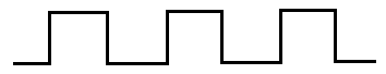
By definition, an astable circuit is that one that oscillators between 2 states, HIGH and LOW, over and over and over again, indefinitely. It never holds one state. It constantly cycles from HIGH to LOW, HIGH to LOW, repeatedly. Therefore, it produces a square waveform signal as output.
To differentiate, a bistable circuit is one that is any 1 of 2 states, indefinitely. It will hold this stable state. This means the circuit will either be LOW or HIGH. However, if a trigger pulse of the correct polarity and amplitude is applied to the circuit, it can switch states.
So, in our circuit, it actually is a bistable multivibrator, but since we're constantly sending trigger pulses to the circuit, it's constantly switching states repeatedly.
So this circuit functions as an astable multivibrator. It's constantly going from ON to OFF, ON to OFF, repeatedly. An astable multivibrator is a multivibrator which has no stable state, so it's constantly switching from ON to OFF, indefinitely.
In this circuit, 2 outputs will be controlled by the circuit, 2 LEDs. They will both flash ON and OFF. While one LED is ON, the other is OFF.
And this is the essence of astable multivibrator functioning.
This can be used for many types of circuits including the classic railway track sign, in which there are flashing LEDs. When one LED is on, the other is off. Then the LED that was ON shuts off and the other LED turns on.
It can be used basically for any circuit in which you want alternating outputs flashing ON and OFF.
We will build this circuit using transistors and a few resistors and capacitors.
Components
- 2 2N2222 transistors
- 2 10KΩ resistors
- 2 510Ω resistors
- 2 100μF electrolytic capacitors
- 2 LEDs
- 2 470Ω resistors
The 2N2222 is a BJT NPN transistor.
The pinout for the 2N2222 is as follows.
Looking at the back of the transistor with the legs pointing downward, the pins are emitter, base, collector (EBC). So again looking at the back where you would see the transistor type engraved, with the words right side up, this will be the order.
The datasheet for it can be found at the following link: 2N2222 NPN Transistor Datasheet.
The other parts we will use are a few resistors and capacitors. You don't have to get the exact absolute values, as long as they are close to the values listed.
The 2 470Ω resistors are used as current-limiting resistors so that the LED doesn't get excess current.
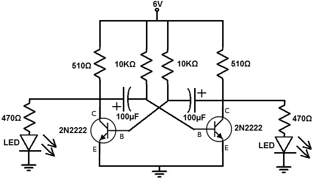
Astable Multivibrator Circuit with Transistors
The astable multivibrator circuit we will build with transistors is shown below.
So we use 2 transistors in this circuit for operation.
The transistors are both 2N2222, which are BJT NPN transistors.
How this circuit works is through the RC network of the resistor and capacitor. The 10KΩ and the 100μF electrolytic capacitor form an RC network that controls the timing of the charging and discharging of the capacitors.
When a capacitor is actively charging up, the transistor that the capacitor is in series with will be OFF. This is the time when the corresponding LED will be OFF. When the capacitor then discharges to the base of the transistor it is in series with, this is when the transistor is on and turns on the LED that it is connected to. So these are the ON and OFF states of the transistors. When the capacitor is charging up, this creates the delay period in which the transistor is off. When the capacitor is discharging, it feeds sufficient current to the base so that the transistor can turn on.
The thing about this circuit is that it alternates output states. While one LED is ON, the other is OFF. What this translates to is while one capacitor is actively charging up, the other capacitor is actively discharging its power. This repeats over and over again.
The discharging of the capacitor current is the trigger pulse which allows the transistor is change state. When the capacitor is charging up, there is no discharge of current to the base of the transistor, so the transistor is OFF. When the capacitor is discharging, there is sufficient current to the base of the transistor and this switches the transistor ON. This discharging current is the trigger pulse to allow output change. So though the circuit is a bistable multivibrator, with these constant trigger pulses created by the discharging of the capacitor, it functions as an astable multivibrator and is able to switch constantly between ON and OFF.
If you want to change the time period that the LEDs turn on and off, then you would adjust the resistor and capacitor values. The time period, T= RC, where R is the resistance and C is the capacitance. So a bigger resistance or capacitance value increases the time period. So if you want the LED ON and OFF for longer periods of time, you would increase either the resistance or capacitance or both. If you want to decrease the time the LEDs are ON and OFF, you would decrease the resistance and capacitance values.
Being that we are using a 10KΩ resistor and a 100μF capacitor, an LED has a time constant of, T= RC= (10KΩ)(100μF)= 1 second. So each LED turns on every second. Being that we have 2 LEDs, an LED in this circuit turns on every half a second. But the individual LEDs themselves turn on every second.
If we wanted to double the time constant of the circuit, we could double the resistance to 20KΩ, while leaving the capacitor value unchanged. This would make an LED turn on every 2 seconds.
So this is how calculations work out. It's the 2 inner resistors and the capacitors that determine the time constant and, thus, frequency of the circuit.
Both resistors and capacitors should be the same value for symmetric coordination of both sides.
Being that you want one LED to be ON and the other to be OFF and for both LEDs to work in symmetry as far as one being ON and the other being OFF,
you want to keep the values equal on both sides. So in this circuit, both resistors are 10KΩ and both capacitors are 100μF. If they weren't equal, there wouldn't
be symmetry. So they should be equal. So keep this in mind when choosing your components.
And this is how an astable multivibrator circuit can work with transistors.
To see how this circuit operates in real life, see the video below.
Related Resources
How to Build a Monostable Multivibrator Circuit with Transistors
How to Build a Bistable Multivibrator Circuit with Transistors