
How to Build an Bistable Multivibrator Circuit with Transistors
In this circuit, we will show how to build a bistable multivibrator circuit with transistors.
To break down what a bistable multivibrator is and does, let's first break down the term into individual components.
First, a multivibrator is a circuit that deals with 2 amplifying devices cross-coupled by resistors and/or capacitors.
Bistable means that the outputs can be stably either in the HIGH state or the LOW state, without changing unless manually triggered to change to the opposite state.
Thus, a bistable multivibrator is a circuit dealing with 2 amplifying devices (we use 2 transistors) that can flip 2 output devices stably to the HIGH or LOW state.
How manual control is achieved in the circuit is through a SPDT switch.
If we adjust the switch, the outputs for each of the transistors switches to the output state.
The circuit is designed so that the 2 outputs are in opposite logic states; so they are not acting in synchrony. If one output device is HIGH, the other is LOW, and vice versa.
Every time we flip the switch, the outputs change to the opposite states. If we don't change the switch, the outputs remain what they are until we do so.
Compare this to comparison to an astable multivibrator circuit, which doesn't stay permanently in any state. An astable multivibrator circuit constantly switches from HIGH to LOW, HIGH to LOW, HIGH to LOW. It does not keep any state permanently. So it is astable, without stability.
A bistable circuit will keep a state unless we trigger it to change states.
In this circuit, we build a bistable circuit with transistors and a few resistors and our output LEDs. We do not use any integrated circuit such as a 555 timer. We can build this circuit completely with simple components.
In this circuit, we will have LEDs as our output devices so that we can see the functioning of the circuit visually. There are 1 SPDT switch that allows us to have manual control over this circuit.
This can be used for many types of circuits including for any type of memory application or storage application. The bistable circuit is a function of a flip flop. It's able to store bits indefinitely unless desired to be changed.
It can be used basically for any circuit in where you want manual control over outputs which you want to keep stable states unless you trigger it to change.
We will show how to build this circuit below.
Components Needed
- 2 2N4401 NPN transistors
- 2 1KΩ resistors
- 2 820Ω resistors
- SPDT toggle switch
- 2 LEDs
The 2N4401 is a popular general-purpose NPN transistor. The datasheet for the 2N4401 transistor can be found at the following link: 2N4401 NPN Transistor Datasheet.
But the 2N4401 transistor is not a requirement. Really any general-purpose NPN transistor can be used such as the more
popular 2N3904 or the 2N2222.
Bistable Multivibrator Circuit with Transistors
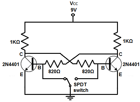
The bistable multivibrator circuit we will build with NPN transistors is shown below.
The breadboard circuit of the circuit above is shown below.
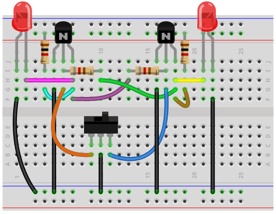
So this is our circuit above.
The circuit is powered by 9V. It can be powered with as little as about 6V but the LED will not be as bright. Therefore, we keep it at 9V.
How this circuit works is through the manual control of the SPDT switch. This switch allows us to switch logic states of the outputs.
If the SPDT switch is turned to the left so that the leftmost transistor is grounded, this cuts off current to the base of the leftmost transistor. This puts the transistor in cutoff, so that no current flows from the collector to the emitter. Therefore, the current flows from the power supply, VCC through resistor the leftmost 1KΩ resistor through the 820Ω resistor to the base of the rightmost transistor, turning that transistor on. The transistor conducts current, powering on the LED connected to the collector of the second, or rightmost, transistor.
If the SPDT switch is turned to the right, the same exact thing occurs but to the other transistor. When the switch is turned to the right, the base of the second transistor is grounded, allowing no power to the base. This puts the rightmost transistor in cutoff. So now current flows from VCC through the rightmost 1KΩ resistor and the 820Ω resistor to the base of the leftmost transistor, turning that transistor on. The transistor conducts, turning on the output LED device.
So the heart of the circuit is alternately grounding the bases of the transistors. Since transistors cannot conduct unless the base receives sufficient power, if we ground the bases, we turn off the transistors.
The circuit wouldn't work properly if none of the bases were grounded. It would create almost random effects as to which LED would turn on.
And if both bases were grounded at the same time, both LEDs would be on. Since in this circuit, we would the LEDs to alternately be on, we don't allow for this situation.
So a single pole double throw switch works perfectly in this situation, with the input connected to ground and the 2 outputs connected to the bases of the transistors.
So this circuit is set up so that only one LED is on at a time. If the LED at one transistor is ON, the other LED is OFF. And vice versa. Every time the switch is changed, each of the LEDs change to the output logic state.
The resistor values aren't written in stone. They can be modified somewhat but should be kept somewhat low.
Some sites and books show this circuit without the 820Ω resistors; in other words, the circuit just has 1KΩ resistors. I personally tested this and it did not work. Resistors need to be connected to the bases of the transistors for the circuit to work.
And as far as modifications to be done to the circuit, you don't have to have LEDs as the output devices. You could change this to be anything, for example, DC motors. You would just have to make sure that there is enough power in the circuit to be able to power on whatever load you want to drive.
And this is how a bistable multivibrator circuit can be built with transistors.
To see how this circuit functions in real life, see the following video below.
Related Resources
How to Build a Monostable Multivibrator Circuit with Transistors
How to Build an Astable Multivibrator Circuit with Transistors