
How to Build a Monostable Multivibrator Circuit with Transistors
In this circuit, we will show how to build a monostable multivibrator circuit with transistors.
A monostable multivibrator circuit is one in which the output of the circuit turns on for a period of time and then shuts off.
The output must be triggered on and it's only turns on once (per trigger) and then shuts off.
It will only turn on each time if there is a trigger.
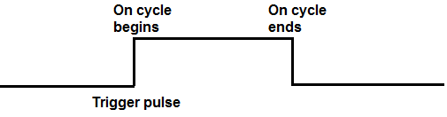
In the absence of a trigger pulse being sent to the circuit, the output stays off, which is its stable state. This is why the circuit is a monostable state circuit. It is always OFF except in the event that there is a trigger. So the stable state of a monstable circuit is off.
We simply use a pushbutton to allow for the trigger that is necessary to turn on the output.
This pushbutton sends a momentary brief HIGH signal that turns on the circuit.
How the circuit works is that the pushbutton that sends a trigger is connected to the base of one of the transistors. Once the base receives this pulse, the transistor turns on, allowing for the capacitor to discharge its charge through the base of another transistor, turning on the load for a period depending on the value of the RC network. In the absence of a trigger pulse, when the pushbutton is unpressed, the capacitor charges up and stays charged. It's the trigger voltage that sets the sequence for the capacitor to discharge through the other capacitor, turning on the output.
We will show how you can modify the amount of time that the output stays on by adjusting the value of the resistor and capacitor.
In this circuit, we will use an LED as the output device, being that it's easy to visualize what's going on through the use of an LED.
Monostable multivibrator circuits can be used for any circuit that needs to be momentarily turned on once. For example, if you are in an exhibit where you want users to press a button to demonostrate the circuit once, this type of circuit can be used. But even more commonplace is any device that you want to operate once with a pushbutton press. Think about how many applications there are. Think of touch toys where you press the stomach and it says something. The toy only talks when you press on it. So this is an example of a monostable circuit. It only does the action one time with a single trigger. Each time you want to activate it again, you would have to trigger it again.
So you can see there are many applications that monostable circuits can be used for.
Components Needed
- 2 2N4401 NPN transistors
- 2 1KΩ resistors
- 10KΩ resistor
- 510Ω resistor
- 470μF electrolytic capacitor
- 10μF electrolytic capacitor
- Pushbutton
- LED
The 2N4401 is a popular general-purpose NPN transistor. The datasheet for the 2N4401 transistor can be found at the following link: 2N4401 NPN Transistor Datasheet.
But the 2N4401 transistor is not a requirement. Really any general-purpose NPN transistor can be used such as the more popular 2N3904 or the 2N2222.
None of the resistor or capacitor values are set in stone. If you don't have the exact value, then
just use values in close range to those that are used above. However, we will show to modify this circuit so that
the output can stay on longer or shorter. Some values will change, while others will stay the same.
Monostable Multivibrator Circuit with Transistors
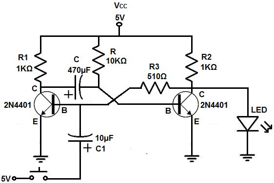
The monostable multivibrator circuit we will build with NPN transistors is shown below.
The breadboard circuit of the circuit above is shown below.
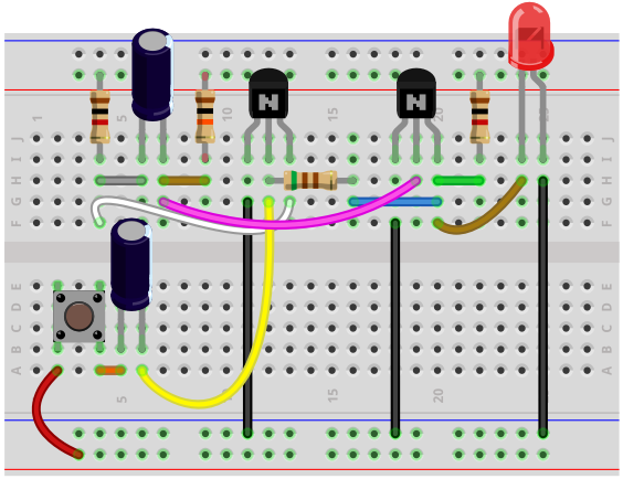
So this is our circuit above.
The circuit is powered by 5V. If you want, you can increase it a little bit to make the LED to be at a more full brightness.
How this circuit works is through the manual control of the pushbutton.
One terminal of the pushbutton is connected to 5V and the other is connected to the 10μF capacitor, which in turn is connected to the base of the leftmost transistor.
When the pushbutton is unpressed, there is no positive voltage going to the base of the leftmost transistor. The base has no power; therefore, the transistor is off. When the leftmost transistor is off, the capacitor does not discharge.
When the pushbutton is pressed, a positive momentary pulse gets sent to the base of the leftmost transistor. This temporary high pulse sets off a sequence of events. Since the base of the transistor now gets enough positive voltage to turn on, the transistor turns on. When this occurs, the capacitor discharges its charge through the base of the second transistor, turning it on. This, turns, on the output LED device.
The period of time that the LED is on for is determined by the RC network. These are the capacitors labeled R and C above, without any numerical values like the other resistors and capacitors. The amount of time that the output device will be on for is approximately equal to, τ= RC. So, in our circuit, using a value of 10KΩ and 470μF gives us a time constant of τ= RC= (10KΩ)(470μF)= 4.7 seconds. So the LED stays on for approximately 4.7 seconds. If you used the same 10KΩ resistor with a 3300μF capacitor, this produces a time constant of, τ= RC= (10KΩ)(3300μF)= 33 seconds. So the LED will be on for approximately 33 seconds.
So, as a rule of thumb, to increase the period of time the output device is on for, you either increase the resistance or capacitance value or both of the RC network. To decrease the period of time the output device is on for, you either decrease the resistance or capacitance value or both of the RC network.
The 2 resistors R1 and R2 on the left and right side of the circuit are also important. They also have an effect on how long the o, thutput device stays on for. These resistor values should be kept relatively low to around 500Ω to 1KΩ. If too high, they decrease the amount of time the output device is on for. If, for example, you made these resistor values 10KΩ, the LED would be on for a much shorter period of time.
The capacitor connected to the base of the leftmost transistor is purely there for debouncing purposes. This capacitor is pretty vital. Without the capacitor, if you were to connect the positive voltage directly to pushbutton, there would be debouncing issues. You could press it multiple times and not get one clean press. Or you could press it on and off by pressing multiple times. The capacitor completely eliminates this. With the capacitor, the circuit can only register one push at a time and that push lasts for the duration of the capacitor discharging. The debouncing capacitor really does work for clean pushbutton presses. A 10μF capacitor works really well.
And of course, as a modification, you can substitute the LED for another output device. You would just have to make sure there is sufficient power to power on that device.
And this is how a monostable multivibrator circuit can be built with transistors.
To see how this circuit functions in real life, see the following video below.
Related Resources
How to Build a Bistable Multivibrator Circuit with Transistors
How to Build an Astable Multivibrator Circuit with Transistors
How to Build a Multivibrator Circuit with a 4047 chip (for astable mode operation)
How to Build an Astable Multivibrator Circuit with a 4049 Inverter Chip