
How to Build a Blinking LED Circuit
In this project, we are going to build a blinking LED circuit with a blinking LED itself.
We've shown in one project how to build an LED Flasher Circuit with a 555 Timer. This is a circuit built with a regular (non-blinking LED) that can flash on and off through the help of a 555 timer chip. We've also shown how to build an LED flasher circuit with an arduino microcontroller. This does the same flashing, only with the help of an arduino microcontroller, not a chip.
In this circuit now, we are building a blinking LED circuit with a blinking LED itself. So we don't need any outside circuitry such as a 555 timer chip or a microcontroller.
In order for this blinking LED circuit to work, we simply need power and a current-limiting resistor, so that the LED doesn't get burnt out.
So, in essence, the circuit is much simpler. We can get blinking of an LED using very minimal components. The downside of this is that this LED blinking or flashing is not nearly as dynamic as using a 555 timer chip or a microcontroller. Through a 555 timer or a microcontroller, we can control the rate at which the LED turns on and off. With a blinking LED, the rate is already determined and can't be changed. So a popular blinking speed may be 0.7 seconds. This is a frequency of 1.5Hz. This is what I've seen on ebay.
So even though a blinking LED requires very minimal setup to get blinking from an LED, it's not as dynamic. But if you simply want a circuit to blink at the speed that the blinking LED is manufactured for, then it is a very great device to use and very easy to set up, much easier than if you were using a chip or microcontroller.
So below we go over how to build this blinking LED circuit.
Components Needed
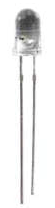
- Blinking LED
- 470Ω Resistor
The blinking LED can be found at numerous places online. Ebay has many sellers that sell them, some in the US, many in China and Hong Kong. It can be obtained for a few bucks, normally because they're sold in bulk.
The blinking LED also be called a self flash LED, so you may come across this name as well. It is a self flash LED.
The 470Ω resistor we use is just to limit current to the LED, so that it doesn't burn out.
Blinking LED Circuit
So now we show how to build the blinking LED circuit.
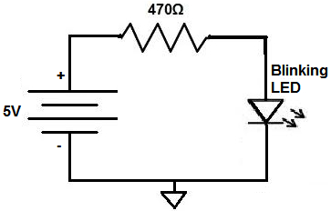
It is a very simple circuit composed of the blinking LED with the current-limiting resistor in series with the LED.
The circuit is shown below.
The breadbooard circuit of the above circuit is shown below.
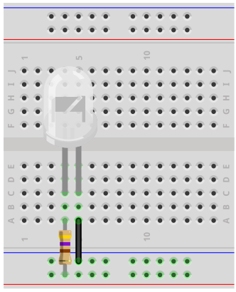
So this is a very simple.
All we need is the blinking LED with a resistor in series with it, so that the LED doesn't get too much current and burn out.
With around 5V going to the LED and a 470Ω resistor in series with it, this produces just about 10mA (5V/470Ω) of current going through the LED. Typically, a blinking LED, or the types that I've seen, can handle up to 20mA of forward current. After this, the LED may get damaged. So voltage and resistor value used are appropriate so that there isn't excess current in the circuit.
As mentioned before, the LED that I purchased that I saw on ebay was 1.5Hz. So this means that is blinks on and off approximately every 0.7 seconds.
And this is all that is required to build a circuit with a blinking LED.
To see this circuit working in real life, see the following video below.