
Capacitive Voltage Divider
A capacitive voltage divider is a voltage divider circuit using capacitors as the voltage-dividing components.
The common type of voltage divider circuit is one which uses resistors to allocate voltage to different parts of a circuit. This is shown
below.
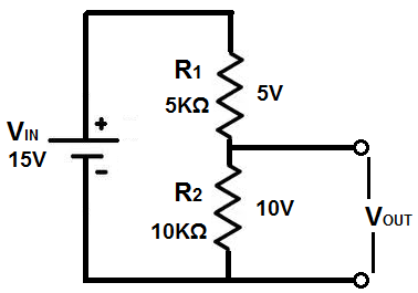
Voltage is divided in a resistor network according to ohm's law. Voltage, V, is allocated to a parts of the circuit depending on the resistance of that part, according to the formula, V=IR, where I is current and R is resistance. Being that current is the same in series circuits, only the resistance will vary. So the resistor in series with the greater resistance will receive the greater voltage.
Capacitors, also, can form voltage divider circuits just like resistors so that voltage can be divided up to parts of a circuit depending on the value of the capacitor.
Just like resistors, capacitors placed in series with a voltage source form a voltage divider network.
Capacitive networks, however, are a little more complex than plain resistive networks, because capacitors are reactive devices. This means that the resistance which capacitors offer in a circuit is dependent on the frequency on the input signal into the circuit. Resistors are nonreactive devices, so their resistance values don't change depending on the frequency of the input signal. However, capacitors do.
So now, we'll discuss how capacitor voltage divider circuits work in both DC and AC Circuits.
Capacitive DC Voltage Divider Circuit
Voltage is divided up in a capacitive DC voltage divider according to the formula, V=Q/C. Therefore, voltage is inversely proportional to the capacitance value of the capacitor. So, the capacitor with the smaller capacitance will have the greater voltage, and, conversely, the capacitor with the greater capacitance will have the smaller voltage.
Below is an example:
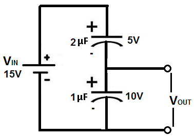
The supply DC voltage in the above circuit is 15V. This means that this 15 volts will be divided across both capacitors so that the voltage dropped across them both will equal
to the 15-volt supply source. Assuming both capacitors hold the same charge, Q, the voltage can be calculated just from the capacitance values of both components. Being that the the 2μF capacitor
is twice the value of the 1μF capacitor, it will have one-half the voltage. Therefore, the 1μF capacitor will drop 10 volts across it, while the 2μF capacitor will drop 5 volts across it.
Capacitive AC Voltage Divider Circuit
Voltage in capacitive AC voltage divider circuits are divided up according to the formula, XC= 1/(2πfc).
To calculate how much voltage each capacitor is allocated in the circuit, first calculate the impedance of the capacitor using the formula above. Once you calculate the impedance of each capcitor, then you can just use ohm's law to find out how much voltage gets dropped across each one.
An example below may help to clarify this:
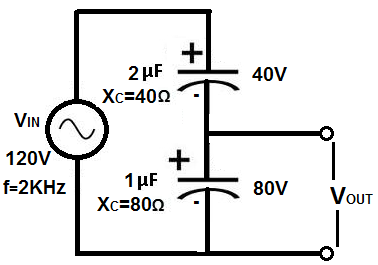
In this circuit above, the AC supply voltage is 120V. Therefore, 120V will be divided between both of these capacitors in series. To calculate how we find each voltage, we first
calculate the impedances of the capacitors. Again, using the reactance formula, XC= 1/(2πfc), we calculate the 2μF capacitor to be XC= 1/(2π(2KHz)(2μF))= 40Ω.
We then calculate the impedance of the 1μF capacitor, which is XC= 1/(2π(2KHz)(1μF))= 80Ω. We now can use a simple voltage divider to know voltage allocation. This makes again
the 1μF capacitor receive double the voltage, which is 80V, in this case, while the 2μF capacitor receives half of that, which is 40V.
Related Resources
Capacitor Voltage Divider Calculator
Capacitor Impedance Calculator
Capacitive Reactance
How to Calculate the Current Through a Capacitor
How to Calculate the Voltage Across a Capacitor
Capacitor Equations