
How to Build a Decade Counter Circuit with a 4017

A decade counter is a circuit in which each of the chip outputs are turned on, one at a time, sequentially or in succession.
Say, if we build a circuit with a decade counter with 10 LEDs. The decade counter will turn on an LED one at a time, unless all t the LEDs have been lit. This is what a decade counter does.
It counts from one to ten. This is what it's labeled "decade" meaning it counts to 10 (just think, a decade is made up of 10 years).
In this circuit, we will connect 10 LEDs to our decade counter chip. The LEDs will light, one at a time, in succession unless all have been turned on. And then it starts the counter over again and repeats over and over infinitely.
A decade counter is a pretty cool chip for the versatility it provides.
The decade counter chip we will use is the popular 4017. A complete description, including pinout, is described below.
Components Needed
- 4017 Decade Counter Chip
- 2 470 resistors
- 47KΩ resistor
- 10KΩ resistor
- 10 LEDs
The 4017 is a 16-pin chip that can be obtained cheaply from a number of online retailers. One place it can be obtained from for very cheap is Tayda Electronics at the following link: Tayda Electronics- 4017 Decade Counter IC.
The pinout for the 4017 is shown below.

10 of the 16 pins are used for output. The output pins are the pins we place the load on that we want the chip to power on. In our case, we are using LEDs, so each one of the LEDs gets attached to one of the output pins. The outputs are numbered 0 to 9. When the circuit is running, they get lit in succession from 0 to 9.
2 of the pins are for power. V+ and GND establish power to the 4017 chip. All the chip is 5V for operation. So we connect V+ to 5V of power.
The remaining pins are Reset, Clock, Enable, and Carry Out.
Reset resets the count back down to output 0. Normally it is grounded, which means the reset isn't active. When it is brought to a HIGH voltage, then it is triggered. So if a circuit is counting up and it's at output 7 and then reset is triggered, it will go back and begin from output 0 once reset is dropped back to ground from a HIGH state. Again, reset is active HIGH but will normally be LOW. If reset is held HIGH, then the output will be stuck at 0 and the count will never be started and advanced.
The clock is a big part of the 4017. Without the clock signal, the 4017 chip will not work. The 4017 chip works off of a clock signal. It advances from one output to the next on the positive (or rising) edge of a clock signal. once the clock goes from LOW to HIGH, at this point the 4017 chip knows to begin and turn on the next output. So it knows when to act based on the clock signal. The faster the clock signal, the faster the 4017 chip executes. So if you have the clock act a certain clock signal frequency and then you make the clock faster, the outputs will trigger on faster. The 4017 directly executes based on the clock speed.
So if you're running the clock at 1Hz, it will turn on the outputs with 1-second intervals between them. If you turn up the clock signal so that it's 5Hz, it will now turn on the outputs with 1/5 of a second interval between, or 200ms. Technically, at 5V, there can be a maximum clock frequency of 2.5MHz. If we fed V+ 15V, a maximum clock frequency of 5.5MHz could be deployed. But for our circuit, if you used clock frequencies this large, you could visually dicipher it, since it would be so fast. So to see it well and slow enough for the human eye, we will use clock signals of about 1 to 10Hz.
The Enable pin is active low, which means it will normally be connected to ground, which makes it active. Held low, the circuit will count up and operate. When this pin is brought HIGH, then all operation stops.
The Carryout pin turns high after output 9 is reached. It remains HIGH for outputs 0 to 4 and goes low from outputs 5 to 9. We will connect an LED to the Carryout pin so that you can see this.
And this accounts for all the pins.
It's very basic. It isn't a difficult chip to understand or use.
It is important to know that only one output is on at a given time and then shuts off, while the next output in line turns on, and this repeats for the 10 outputs that the 4017 chip offers.
So if we are lighting up LEDs and we have 10 LEDs, each of the LEDs will light up, one at a time, until all 10 LEDS have lit up. Then the decade counter will start all over again, going from 0 to 9 again, in an infinite loop.
It is called a decade counter because it counts up to 10, from output 0 to output 9.
4017 Decade Counter Circuit
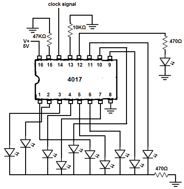
The schematic diagram for the decade counter using the 4017 chip is shown below.
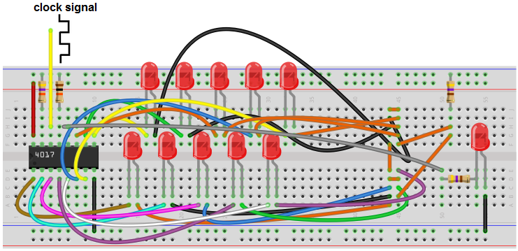
The breadboard schematic of the above circuit is shown below.
The first step is to connect power to the 4017 chip. 5V goes into pin 16 of the chip and pin 8 gets grounded. This establishes sufficient power for the operation of the chip.
Next LEDs are connected to each of the outputs and the carryout pin. A 470Ω resistor is used with the 10 LEDs connected to the output and the carryout pin to limit current to the LED so it doesn't burn out.
The reset pin and the enable pin are both kept low for circuit operation. But to test them you can rewire them from ground to the positive voltage rail to see how the circuit reacts. What you should see when reset is temporarily high and then shifted back to ground is that the count begins from the start at output 0 and then counts back up. Basically it resets all over from the beginning. If you set enable high, the count will freeze.
For this circuit to work, we need a clock signal. The easiest way to get this clock signal is through a function generator. With a function generator, you can easily produce digital (square) signals and set and adjust the frequency to whatever you want. In our case, we would set it to 1Hz. 1Hz is one cycle per second. So that's one low and one high per second. You will be able to see a new LED light up each second. After this, you can adjust either higher or lower. If you make the frequency larger, then the cycle speeds up. The outputs will advance quicker, so the LEDs will light up successively faster. If you make the frequency lower such as 0.5Hz, then the period, T, will be T= 1/f= 1/0.5Hz= 2 seconds. Now there will be 2 seconds between an LED turning on.
If you don't have a function generator, then your next bet is to build a voltage-controlled oscillator in order to produce a clock signal. The chip that's used to build a voltage-controlled oscillator is a 4046 phase-locked loop. This chip, if configured right, will produce digital (square) waves at pin 4. Thus, pin 4 of the VCO circuit should be connected into pin 14 of the 4017 chip.
When run, each LED should light one at a time, starting from output 0 going to output 9. This will repeat over and over in an infinite loop.
Related Resources
How to Build a Light Detector Circuit with a NAND Gate Chip
How to Build a Night Light Circuit with a NAND Gate Chip
How to Build a NAND Gate Circuit Using a 4011 Chip