
Diode Approximations
Diode approximations are a way to analyze diodes in circuits.
In all approximations, the diode acts as a switch.
There are 3 approximations that are used for diodes.
First Approximation
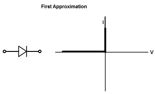
The first approximation is viewing the diode as an ideal diode. With this first approximation, the diode acts as a perfect switch that doesn't consume any voltage and doesn't have any internal resistance.
It is not used for real-life situations but just as general approximations when preciseness isn't needed.
For certain circuits where the forward voltage needed to turn on diode is seen as trivial,
the first approximation can be adopted and used.
Second Approximation
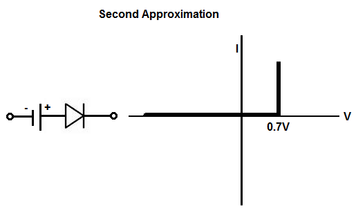
In the second approximation, the diode is seen as as a diode that needs voltage in order to turn on.
For a silicon diode, the diode needs about 0.7V in order to turn on. When the voltage
fed into the diode forward biased is 0.7V or greater, the diode switches on. When the voltage is less than 0.7V, the
diode turns off.
Third Approximation
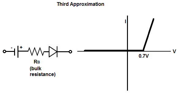
In the third approximation, the diode is seen as a diode that consumes 0.7V (for silicon diode) and voltage across the internal bulk resistance of the diode.
This is most real-world form of a diode and is usually used when a circuit is in design, especially an intricate circuit. For basic circuits, the second approximation may be used; this is especially true when the load resistance is high, because the bulk resistance is usually very low, such as less than 1Ω. The third approximation is crucial if the load resistance is very low.
The bulk resistance, RB, of a diode is the approximate resistance across
the terminals of the diode when a forward voltage and current are applied across the diode.
The bulk resistance represents the resistance of the p and n materials of the p-n junction of the diode.
The bulk resistance is not a fixed resistance but a dynamic one. It changes according to the amount of
forward voltage and current going through the diode at any particular time, according to the formula,
RB= ∆VF/∆IF
. RB is a very small resistance, usually less than
1Ω and almost always less than 10Ω.
Let's now take 2 examples at both sides of the extremes of how the bulk resistance can affect a circuit, depending on the load resistance of the circuit.
Let's say the bulk resistance for both circuits is 1Ω and the power source powering the circuits is 5V.
The first circuit has a load, which has a resistance of 1KΩ.
According to this circuit, the (silicon) diode will consumes its normal 0.7V to operate and 0.004995V. This is because if 1Ω/(1Ω + 1KΩ)= 0.000999 and 4.3(0.000999)= 0.0042957V. Even if the output resistance is 75Ω, the diode will only consume 0.0658V more on top of 0.7V. This is because 1Ω/(1Ω + 75Ω)= 0.0131589 and 4.3V(0.0131589)= 0.05658.
Now let's look at a circuit that has a load with a very low resistance, let's say 1Ω. The situation will be much different. So the diode will consume its necessary 0.7V and an additional 2.15V. This is because voltage division between 1Ω (bulk resistance of the diode) and 1Ω (load resistance of the circuit) gives 1Ω(1Ω + 1Ω)= 0.5 and 4.3V(0.5)= 2.15V. Therefore, the voltage divides up by dropping 2.85V across the diode and 2.15V across the (1Ω) load. Therefore, you can see that the voltage the diode now consumes is great because the load resistance is so small.
So when the resistance is so small, the bulk resistance has to be
taken into effect. If the load resistance is fairly large (several ohms or greater), then the
bulk resistance is not as important.
So this is a basic summary of the approximations of diodes.
Related Resources
Types of Diodes
How Does Current Flow Through a Diode?
What is a Diode Connected in Forward Biased?
What is a Diode Connected in Reverse Biased?
What is the Leakage Current of a Diode?
How to Build a Diode Clipper Circuit
How to Build a Diode Clamper Circuit