
How to Build a Simple Force Sensing Resistor (FSR) Circuit
In this article, we will go over how to connect a force sensing resistor, or force sensitive resistor, (FSR) to a circuit to build many different types of useful circuits with them.
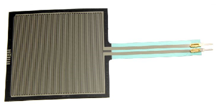
Force sensing resistors are variable resistors which change resistance according to the pressure or force applied to them. Under no force, the resistance is very high, pretty much infinite. When a light pressure is applied to the sensor, its resistance drops to about 100KΩ. When maximum pressure is applied, its resistance drops to about 200Ω.
So with no pressure or weight applied, the FSR circuit will be essentially open because its resistance is so high.
With a good amount of pressure applied, about 20lbs needed, the resistance drops dramatically and can go as low as 200Ω.
We will use the basic functioning principles that FSRs have to create a meaningful circuit.
We will wire an FSR to an arduino board. We wire a 10KΩ resistor in series with the force sensing resistor in order to create a voltage divider. One terminal of the FSR will connect to the 5-volt voltage supply of the arduino board and the other terminal will connect to ground. The 5 volts of voltage will be divided based on the resistance of the fixed resistor and the FSR. The fixed resistor will always stay 10KΩ. However, the FSR serves as the variable resistor. It will change resistance based on the pressure applied to its surface. When there is no pressure applied, its resistance is very high, so most of the voltage falls across it rather than the 10KΩ resistor. When it is pressed against with maximum pressure, its resistance falls to near 200Ω, so most of the voltage falls across the 10KΩ resistor and not the FSR.
Based on these voltage divisions, we can get readings of how much pressure it is being applied to the FSR. If a high voltage is across it, we know that it barely has any pressure applied to it. If a low voltage is across it, then it has a lot of pressure applied to it. The arduino serves as a microcontroller that can give us "pressure" readings of the FSR circuit.
This type of circuit could be useful for a wide range of real-life scenarios. Think of a car seat that is equipped with a seatbelt light on the car dashboard. How does it know to light the dashboard, indicating that the passenger seatbelt is not on? How does it know that a passenger is present in the passenger seat or not? It knows because it detects weight. If it detects weight and the seatbelt is not on, the seatbelt LED on the dashboard lights up, indicating that the seatbelt is not on.

We could apply this circuit that we're going to build for a situation such as the car seatbelt lights. If our FSR has a very low voltage, this indicates
that a lot of pressure is being applied to it. This would indicate that a passenger is present in the seat. If this is the case and the seatbelt is not on, this would
trigger the passenger seatlight light to turn on in the dashboard.
Components Needed
- Force sensing resistor
- 10KΩ Resistor
- Arduino Board
The force sensing resistor can be obtained from many different online retailers. It can be bought in a circular form or square form.
We will use 5 volts of power from the 5V terminal of the arduino.
FSR Circuit
The circuit we will build is shown below:
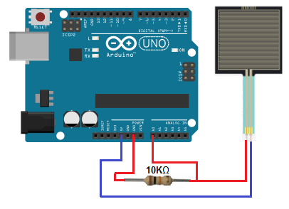
Again, the 10KΩ resistor is in series with the FSR. This forms a voltage divider circuit with the 5 volts powering it. This 5 volts will be divided
between the 2 components, based on the resistance of each of the components. Based on the voltage across the components, the arduino board can read how much pressure
is being applied to the FSR.
Code
The code for the arduino to obtain pressure readings of the FSR is shown below.
int FSR = A0;
void setup(){
Serial.begin(9600);
}
void loop(){
int FSRValue = analogRead(FSR);
Serial.println(FSRValue);
delay(5000);
}
So this is basic arduino code that takes and prints out the analog value across the FSR. Since the FSR is connected to arduino terminal pin 0, we set it equal to A0 in our code. We then read the value of using the analogRead() function and then display this value using the Serial.println() function. We use the delay() function to give readings every 5 seconds. You can modify the time if you want readings given more or less frequently.
Of course, we can modify the code and hardware of this circuit to do a much wider range of activities. For example, instead of simply reading the value of the FSR and displaying it, we can read the value and use if statements to make choices. For example, if the reading is below a certain threshold, a certain event can take place. If the reading is above a certain threshold, another event take place. For example, we can connect an LED to a digital pin of the arduino. If the reading is below a certain level, the LED is off. If the reading is above a certain level, the LED turns on.
An FSR is very useful when imprecise pressure readings need to be determined, such as in the scenarios mentioned
above.
Related Resources
How to Build a Hall Effect Sensor Circuit
How to Build a Motion Detector Circuit
How to Build a Vibration Detector Circuit