
How to Build a DC Power Supply
In this project, we will show how to build a simple DC power supply, which can be used to supply adjustable DC voltage to an electronic circuit.
By going through this project, you will gain understanding of how a DC power supply works and what parts are needed to create a simple DC power supply.
If you've been doing any circuitbuilding or electronic engineering technician work, you know how important a DC power supply is. It can be used to produce adjustable DC voltages. So instead of using a plethora of batteries for a circuit or wall warts, switching out batteries to get the precise voltage, you can simply use a DC power supply, which greatly simplifies providing DC power to a circuit.
So in order to build a DC power supply, we will need the following components:
Components Needed
- AC Plug
- 24V Transformer
- Full Wave Bridge Rectifier
- LM317 Voltage Regulator
- Heat Sink
- 2200μF electrolytic capacitor
- 100μF electrolytic capacitor
- 240Ω Resistor
- 3.6KΩ Potentiometer
DC Power Supply Schematic Diagram
Above are the parts needed to create a DC power supply.
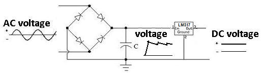
Below is the schematic for the DC power supply, so that we can see how all the parts are connected and are brought
together:
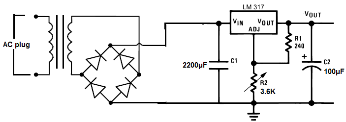
We'll now go over each part of this circuit and go over the role each component plays, so that you can know how this circuit
works in its entirety.
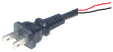
AC Plug- The first part of the circuit is the AC plug. When we create a DC power supply, it creates DC voltage from
the AC mains voltage from a wall outlet. To build a DC power supply, purchase a 3-prong AC plug. It can also work with a two-prong AC
plug. But having a 3-prong plug is better because ground provides better against possible electric fires.
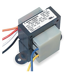
Transformer- After the AC plug, we need a step-down transformer. The tranformer's job is to take the 120V AC voltage from the mains
line and step it down to 24 volts.
This is because our DC power supply will supply variable DC voltage of 1-20V. Therefore, we lower the very high voltage that we get from the mains outlet from the wall into a smaller voltage.
It must still exceed the voltage of the DC which we want to output. Since we want to create up to 20VDC variable voltage output, we need a transformer that converts the mains voltage to a voltage
that is higher than this 20V. A step-down transformer is a great device for lowering voltage from a mains AC voltage line.
Full-wave Rectifier- The next component we need in our circuit is a full-wave rectifier. The job of the full-wave rectifier is to take the AC voltage from the transformer and rectify it so that the voltage no longer goes through a negative cycle. With the rectifier, all of the voltage is rectified positive.
Below is the how the voltage looks before and after the full-wave rectifier:
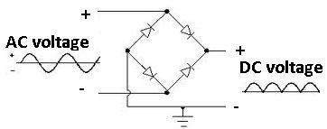
You can see how all voltage waveforms are now above the positive line. This is called pulsating DC voltage. We will later add more components so that this can be a nearly perfectly smooth DC output, which is what is desired.
For more in-depth information about connecting full wave rectifiers, see
How to Connect a Full-wave Rectifier.
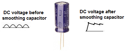
Smoothing Capacitor- The next component after the full-wave rectifier is the smoothing capacitor. The smoothing capacitor acts to smooth out fluctuations in a signal, so that there is less fluctuation. As you saw in the previous component, the rectifier creates pulsating DC signals. The smoothing capacitor, now, a 2200μF capacitor, acts to even out this pulsating fluctuations to create a smoother waveform.
The diagram below shows how the voltage waveform looks before and after the smoothing capacitor:
For more in-depth information about smoothing capacitors, see What is a Smoothing
Capacitor?.
LM317 Voltage Regulator- After the smoothing cap is the LM317 Voltage Regulator.
This regulator serves a twofold purpose. First, it serves to further smooth out the fluctuating signal, so that it's a perfectly smoothing DC signal.
A regulator is a device that "regulates" voltage so that a perfectly smoothing DC voltage is output.
Below is a diagram of a voltage waveform after both a smoothing capacitor and a voltage regulator:
The second purpose of the LM317 regulator, since it is an
adjustable voltage regulator, is to produce variable DC voltage as output. How we vary voltage is by changing the resistor R1 and the potentiometer R2.
R1 Resistor and R2 Potentiometer- The next components needed are the R1 resistor and R2 potentiometer. These
two used together decide what voltage will be output by the regulator. The formula is VOUT= 1.25V (1 + R2/R1). So if R2 is turned
all the way so that its resistance is near 0Ω, the voltage output will be just over 1V. When the potentiometer is turned so that its resistance is 3.6KΩ, the voltage output will be about
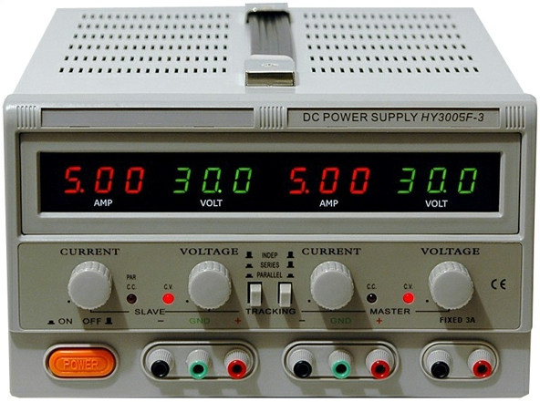
20V. This potentiometer decides how much voltage is output, just like how you turn the knob of a professional-made DC power supply. If we chose a higher voltage-valued step-down transformer,
such as a 36V step-down transformer and used a higher-valued potentiometer, we could increase the amount of DC voltage output, from, say, 20V to 30V or more.
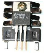
Heat sink- One thing we must do to the voltage regulator is attach a heat sink to it. This is vital for this application.
This is because when we use a regulator, we input a voltage into it and it outputs the voltage, based on the values of resistor R1 and potentiometer R2. When the potentiometer is at its highest resistance, it doesn't dissipate that much heat. Since our transformer outputs 24V, when the potentiometer is set to 3.6KΩ, the regulator outputs 20V. 24-20V=4V. Thus, not that much wasted voltage is created. However, if the potentiometer is set to near 0Ω, the regulator outputs approximately 1.25V. 24V-1.25V=22.75V of wasted, dissipated energy. This creates a lot of heat, since the voltage difference between input and output voltage is so great. Any difference appears as heat. So the greater the difference, the greater the heat. This is the r reason it is vital to attach a heat sink to the regulator. When the difference between input and output voltage is great, it appears as heat. We must have a way to dissipate this heat, or else it can damage or destroy the circuitry of the power supply. The way to do this is to use a heat sink. This is the reason why professional DC power supplies always have large heat sinks in the back of them.
For more information about attaching heat sinks to voltage regulators, see
Why to Attach a Heat Sink to a Voltage Regulator.
C2 Capacitor- The C2 capacitor acts again as a load balancer. It helps to smooth out any fluctuations that may exist on the output of the regulator.
And this is how a simple DC power supply can be built that allows for voltage adjustment.