How to Connect a Single Pole Single Throw (SPST) Relay in a Circuit
In order to know how to connect a single pole single throw(SPST) relay, you must know what each pin terminal represents and how the relay works.
Terminal Pins
A Single Pole Single Throw Relay comes with four terminal points.
The terminals are COIL, COIL, COM, and N.O.
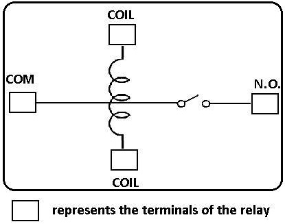
This correlates to the following in the relay:
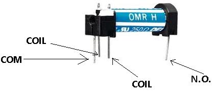
Terminal Descriptions
-COIL- This is one end of the coil.
COIL- This is the other end of the coil. These are the terminals where you apply voltage to in order
to give power to the coils (which then will close the switch). Polarity does not matter. One side gets positive
voltage and the other side gets negative voltage. Polarity only matters if a diode is used.
NO- This is Normally Open switch. This is the terminal where you connect the device that you
want the relay to power when the relay is powered, meaning when the COIL receives
sufficient voltage. The device connected to NO will be off when the relay has no power and will turn on when the relay receives power.
COM- This is the common of the relay. If the relay is powered and the switch is closed,
COM and N.O. have continuity. This is the terminal of the relay where you connect the first part of your circuit
to.
Now that we know what each terminal pin represents, we now wire it to a circuit for it to do a real-world function. We're going to connect a single pole single throw relay to a circuit to light up a LED.
This is the circuit below to connect a single pole single throw relay to light a LED:
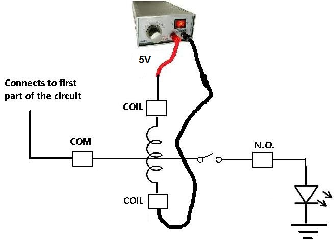
Since the relay is rated for 5V, it should receive 5 volts in order to power on. It may work with less voltage, but 5V is really what it should receive. This goes into either side of the COIL terminals. Even if you switched the positive and negative voltage of the power supply, it should work exactly the same.
The COM terminal of the relay gets connected to the first part of the circuit. If there is no first part of the circuit, this terminal can be left open.
The N.O. terminal of the relay gets connected to the output of the device that it powers on
or off. In this case, we are using a LED as output. When the relay receives 5V of power in its coil, the
LED will light up. If the 5v are cut off from it, the LED will no longer light.
To see how this circuit works in a real-life setting, see the following video below.
Related Resources
Types of Relays
Relay Terminals
Relay Wiring Diagrams
SPST Relay Wiring Diagram
How to Connect a Single Pole Double Throw (SPDT) Relay to a Circuit
How to Connect a Double Pole Double Throw (DPDT) Relay to a Circuit
How to Build a Relay Driver Circuit
How to Test a Relay
How to Test the Coil of a Relay
How to Test the Relay Contacts