
How to Build a Relay Driver Circuit

A relay driver circuit is a circuit which can drive, or operate, a relay so that it can function appropriately in a circuit.
The driven relay can then operate as a switch in the circuit which can open or close, according to the needs of the circuit and its operation.
In this project, we will build a relay driver for both DC and AC relays. Since DC and AC voltages operate differently, to build relay drivers for them requires slightly different setup. We will also go over a generic relay driver which can operate from either AC or DC voltage and operate both AC and DC relays.
All the circuits are relatively simple to understand.
DC Relay Driver Circuit
We will first go over how to build a relay driver circuit for relays which operate from DC power.
To drive a DC relay, all we need is sufficient DC voltage which the relay is rated for and a zener diode.
All relays come with a voltage rating. This is called on a relay's datasheet its rated coil voltage. This is the voltage needed in order for the relay to be able to operate and be able to open or close its switch in a circuit. In order for a relay to function, it must receive this voltage at its coil terminals. Thus, if a relay has a rated voltage of 9VDC, it must receive 9 volts of DC voltage to operate. So the most important thing a DC relay needs is its rated DC voltage. If you don't know this, look up what relay you have and look up its datasheet and check for this specification.
And the reason why a diode is needed is usually because it functions to eliminate voltage spikes from a relay circuit as the relay opens and closes. The coil of a relay acts an inductor. Remember that inductors are basically coils of wires wrapped around a conductive core. This is what relay coils are as well. Therefore, they act as inductors. Inductors are electronic components that resist changes in current. Inductors do not like sudden changes in current. If the flow of current through a coil is suddenly interrupted, for example, a switch opening, the coil will respond by producing a sudden, very large voltage across its leads, causing a large surge of current through it. From a physics or physical perspective, this phenomen is a result of a collapsing magnetic field within the coil as the current is terminated abruptly. Mathematically, this can be understood by noticing how a large change in current (dI/dt) affects the voltage across a coil (V=LdI/dt). Since we are opening the switch, in this case, the current literally goes from full mode to 0 instantaneously. This creates a large voltage spike. Surges in current that result from inductive effects can create very high voltage spikes (as high as 1000V) that can have nasty effects on neighboring devices with in the circuits, such as switches and transistors getting zapped. Not only are these voltage spikes damaging to other electronic components in a circuit but thye are also damaging to the relay's switch contacts. The contacts will suffer from these spikes as well.
So how do we prevent these voltage spikes? How can we suppress them so that they don't cause this damage? The answer for DC relay circuits is to use a diode. A diode is placed reverse biased in parallel with the relay. The diode acts as a transient suppressor. A transient is a spike. A transient suppressor suppresses these spikes. Placing a diode in reverse bias across a relay's coil eliminates voltage spikes by going into conduction before a large voltage can form across the coil. In other words, a diode will conduct current in reverse bias once the voltage reaches a certain threshold and shunt the current to ground. Once the diode begins conducting, it no longer holds voltage. So that the relay in parallel will not receive the excess voltage. So the diode functions to shunt excess power to ground once it reaches a certain threshold. Diodes are devices that do not conduct in reverse. However, if the voltage reaches a certain level, called the breakdown voltage, it will conduct. This is a good thing, when we need the diode to act as a transient suppressor, because it forces all excess power to ground, as to not affect any other parts of the circuit.
The diode must be rated to handle currents equivalent to the maximum current that woudl have been flowing through the coil
before the supply current was interrupted. Therefore, if the relay normally passes a certain amount of current through it during normal operation,
the diode must be rated for a current rating above this value, as to not stop normal operation.
Components Needed
- DC Relay
- Zener Diode
- DC Voltage Source
Again, the DC relay must receive its rated voltage value in order to operate.
The DC power source can be either batteries, wall wart power, or a DC power supply- any DC power source.
The zener diode is placed reverse biased in parallel to the relay.
DC Relay Driver Circuit Schematic
Below is the DC relay driver circuit which we will build:
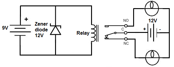
The relay which we use in this case is rated for 9V. Therefore, a 9-volt DC voltage source feeds the resistor. To suppress transients
that may be caused by the relay opening and closing, we place a zener diode reverse biased in parallel with the relay. This will shunt all
excess power to ground once it reaches a certain threshold. This is all that is needed to operate the relay. With sufficient power, the relay will
now closed, driving the loads that are connected to its output.
How to Build an AC Relay Driver Circuit
Now we will show how to build an AC relay driver circuit.
This is a relay which is run, not off of DC power, but AC power.
To drive an AC relay, all we need is sufficient AC voltage which the relay is rated for and again a transient suppressor.
Unlike DC relays, however, you cannot use a diode to to eliminate voltage spikes. With AC power, the diode will conduct on alternate
half-cycles. Using 2 diodes in reverse parallel will also not work because the current will not make it to the coil of the relay. The current will
just go through the diodes. Instead, to create a working transient voltage suppressor with an AC circuit, we use an RC series newtwork placed across the coil in parallel. The capacitor absorbs
excessive charge and the resistor helps to control the discharge.
Components Needed
- AC relay
- 0.05µF capacitor
- 100Ω Resistor
- AC Voltage Source
The AC voltage source will likely come from a plug plugged into a US wall outlet.
Warning: Be very careful with AC power coming directly from a wall outlet because it is lethal enough to cause shock. Please
consult a professional before taking power directly from a plug in a wall outlet.
AC Relay Driver Circuit
The AC relay driver circuit we will build is shown below:

We, again, feed the AC relay the AC voltage it is rated for. If we use a relay with a rated voltage of 110VAC, we must feed it
110V from an AC power source. The capacitor and resistor in series acts as the transient voltage suppressor to suppress voltage spikes. This first
half of the circuit serves as the relay driver. With the relay now having sufficient power, it will turn on and power the loads it is connected to.
Generic Relay Driver Circuit
The last relay driver circuit we will show is one which can be driven by an arbitrary control voltage.
This is a relay driver circuit which can be driven by either AC or DC input voltage. And unlike the other circuits,
a specific voltage,
such as the rated voltage values we used to drive the others, does not need to be used. Because this circuit contains a transistor, much less power
needs to used on the input side to drive it.
Components Needed
- 6-9V Relay
- 2N2222 Transistor
- Zener diode
- 1KΩ Resistor
- 9V Battery or DC Power Supply
- Another input voltage source
Relay Driver Circuit
The circuit we will build is shown below:
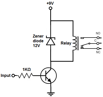
Now that we're using a transistor to drive the relay, we can use considerably less power to get the relay driven. Because a transistor is an amplifier, we just have to make sure that the base lead gets enough current to cause a larger current to flow from the emitter of the transistor to the collector. Once the base receives sufficient power, the transistor will conduct from emitter to collector and power the relay.
With no voltage or input current applied to the transistor's base lead, the transistor's emitter-to-collector channel is open, hence blocking current flow through the relay's coil. However, if sufficient voltage and input current are applied to the base lead, the transistor's emitter-to-collector channel will close, allowing current to flow through the relay's coil.
The benefit of this circuit is a smaller and arbitrary (DC or AC) current can be used to power the circuit and the relay.
Related Resources
How to Connect a Relay to a Circuit
How to Connect a Single Pole Single Throw (SPST) Relay to a Circuit
How to Connect a Single Pole Double Throw (SPDT) Relay to a Circuit
How to Connect a Double Pole Double Throw (DPDT) Relay to a Circuit
How to Build an LED Driver Circuit