
How To Test a Transistor
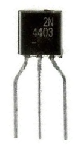
In this article, we will go over different tests that we can use to determine whether a transistor is good or not, all by utilizing the ohmmeter of a digital multimeter.
A transistor, internally, is basically a component made up of different diode junctions. NPN and PNP Transistors are made up two pn junctions sandwiched together. These pn junctions are diodes.
Knowing that transistors are essentially diodes sandwiched together (placed back-to-back), we can exploit this principle and test the leads of transistors as if they are separate diodes. If you want to learn more about diode testing, check out how to test a diode.
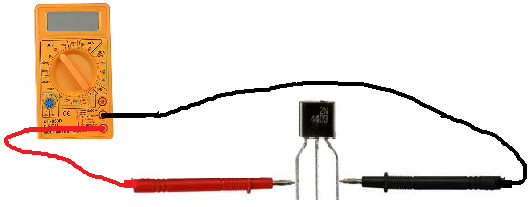
To test a transistor, we measure one diode junction with the multimeter leads situated one way and then we flip the leads of the multimeter
to the reverse position, to switch polarity. One side of the diode junction should read a very high resistance, above 1MΩ of resistance (the anode-to-cathode side) and the
other side should read a much lower resistance, maybe of a few hundred thousand ohms (the cathode-to-anode side).
This we do for each junction.
So in total we'll have six readings, which are shown below:
- Emitter to base
- Base to emitter
- Emitter to collector
- Collector to emitter
- Collector to base
- Base to collector
Each pair should have one side with very high resistance (>1MΩ), and the other side with a much lower resistance of a few hundred thousand ohms.
If this is the case for all the transistor leads, the transistor is good.
If not, the transistor is defective.
Related Resources
How to Test a Zener Diode
How to Test a Relay
How to Test a Voltage Regulator
How to Test a Battery
How to Test a Fuse
How to Connect a Transistor as a Switch in a Circuit
Transistor Schematic Symbols
BJT vs FET (Transistors)
JFET vs MOSFET (Transistors)
How to Connect a Transistor in a Circuit for Amplification