
How to Build an Infrared Proximity Switch Circuit with a NAND Gate
In this project, we will build an infrared proximity switch circuit using a 4011 NAND gate chip.
An infrared proximity switch sensor is a switch which will activate when the sensor detects an object, meaning it will activate if an object or anything at all goes in front of the sensor.
The infrared proximity switch sensor is a reflection-type photoelectric snesor which sends and receives infrared beams. Infrared proximity switches work by sending out beams of invisible infrared light. A photodetector on the proximity switch detects any reflections of this light. These reflections allow infrared proximity switches to determine whether there is an object nearby. When the infrared is able to read back the infrared beams that it sends out, then this means the path of the infrared is impeded, which means there is an object nearby. When the infrared sensor cannot read back the infrared beams it sends out, this means that the path is unimpeded and there is no object in front of the sensor, which is why it cannot read back the infrared beams it is sending out.
Normally, when the sensor is unblocked (no object in front of it), the sensor will output a HIGH signal (about 3.5V) on its signal line. When an object blocks the sensor so that the sensor can read back the infrared beams, then the sensor will output a LOW signal (0V) on its signal line.
This drastic change in voltage makes it very easy for a logic chip such as a NAND gate logic chip to read these voltages.
A NAND gate triggers on when fed a voltage near 0V and turns off when fed a voltage above half of that fed into its VCC pin. Since the sensor outputs a LOW signal (near 0V) when it detects an object, a NAND gate detects this and outputs a HIGH signal on its output that can turn on a load. We will explain, in detail, exactly how this works when showing the schematic below in case you don't understand now.
In this circuit, we will make it so that an LED lights up whenever an object is in front of the sensor.
An infrared proximity switch such as the one we are using in this circuit has great application for real life. The sensor can detect
any type of moving objects, so it can act as a motion detector circuit.
Components Needed
- Infrared Proximity Sensor Switch
- 4011 NAND Gate Chip
- 330Ω resistor
- LED
The infrared proximity sensor switch can be obtained from ebay for about $5 normally.
It operates on 5V of power.
The distance the sensor can detect an object is between 3cm-80cm, and this distance is adjustable, so that if you want the sensor to only be triggered when within 10cm of the sensor, you can do so.
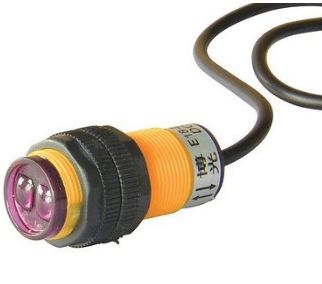
The infrared sensor is a 3-terminal device.
There is a red, green, and yellow wire.
The red wire is the +5V line. It connects to 5V of power.
The green wire is the GND line. It connects to the GND terminal of the power supply.
The yellow wire is the signal line. It connects to the input of the NAND gate chip. Being that it only outputs 2 values, LOW or HIGH, it is a digital input. The 4011 NAND gate chip will either read it as LOW or HIGH. Know that the signal on this sensor is active low. When the sensor does not detect any object, it outputs a HIGH signal. When it detects an object, it outputs a LOW signal (0v).
The 4011 quad NAND gate chip can be obtained very cheaply from a number of online retailers for just a few cents. One place it can be obtained from is Tayda Electronics at the following link: Tayda Electronics- 4011 Quad 2-Input NAND Gate IC. However, it is a very popular chip and many electronics parts suppliers have them.
The pinout of the 4011 is shown below, so that you can see how to connect it in the circuit.
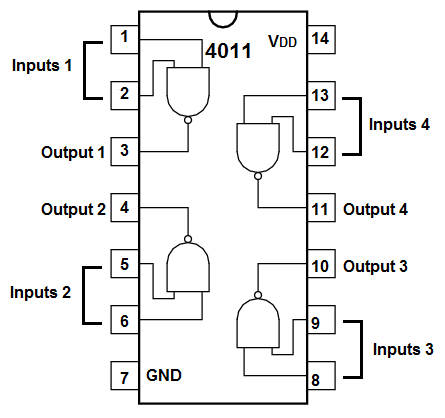
Each NAND gate has input pins and 1 output pin.
The following chart shows NAND gate logic, which shows what output a NAND gate chip will produce for a set of given inputs.
| NAND Gate Logic | ||
| Inputs | Output | |
| 0 | 0 | 1 |
| 0 | 1 | 1 |
| 1 | 0 | 1 |
| 1 | 1 | 0 |
This means that if one of the inputs are a 0, the NAND gate will output a logic HIGH at its output, which means the output will be drawn up to VCC and the load will be powered. If both inputs feeding into the NAND gate are a 1, only then will the NAND gate output a logic LOW at its output, which means the output will be drawn down to GND, and the load will not be powered.
In our circuit, we will use both of these cases.
The other components we need are the LED and the 330Ω resistor in series to limit current to the LED so that it doesn't burn out.
Infrared Proximity Switch Sensor Circuit Using a 4011 NAND Gate Chip
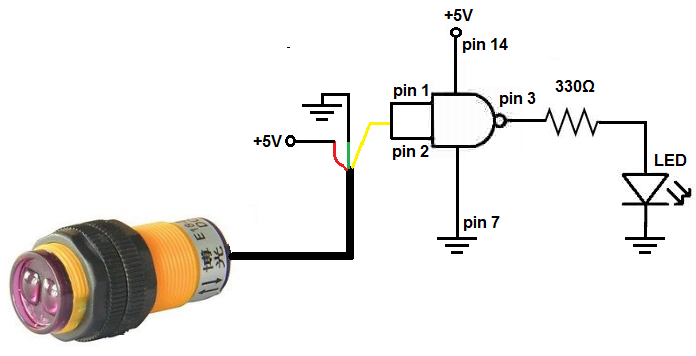
The schematic diagram of the infrared proximity switch circuit using a 4011 NAND gate chip is shown below.
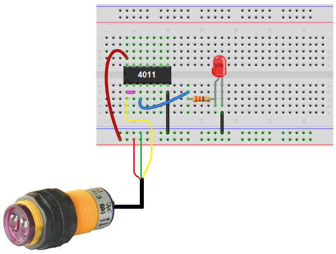
The breadboard schematic of the circuit above is shown below.
The circuit schematic is basic.
First, we must connect power to the NAND gate. We connect 5 volts of power to VCC of the 4011, which is pin 14. We connect pin 7 to GND. This establishes power to the NAND gate.
For our circuit, we simply use one NAND gate. The inputs are pins 1 and 2. And the output is pin 3.
We tie the inputs together, so both inputs share the same signal. So if the input is HIGH, both are HIGH. If the input is LOW, both are LOW. We do this so that when the input is HIGH, meaning the infrared proximity sensor has not detected an object, the output will be low. Remember NAND gate logic: when both inputs are HIGH, the output is LOW.
We connect the red wire of the infrared proximity switch sensor to the power line on the breadboard, which gives the sensor 5V, which is its operating voltage needs. We connect the green (or black wire) to GND. And then we connect the yellow wire of the sensor to either of the inputs of the NAND gate. It doesn't matter, since both are commonly connected. We connect a
When no object is in the sensor's path, it sends out a HIGH signal on its signal line of about 3.5V. When it does this, the NAND gate outputs a LOW signal at its output and the LED does not turn on.
When an object is in the sensor's path, the sensor sends out a LOW signal on its signal line of about 0.07 (essentially 0V). When it does this, the NAND gate outputs a HIGH signal at its output and the LED turns on.
And this is how an infrared proximity switch can work with a NAND gate.
To see how this circuit works in real life, see the following video below.
Related Resources
How to Build a Light Detector Circuit with a NAND Gate Chip
How to Build a Night Light Circuit with a NAND Gate Chip
How to Build a NAND Gate Circuit Using a 4011 Chip