
How to Build a Dark-activated Light Circuit
In this project, we will go over how to build a dark-activated light circuit.
This is a circuit whose light will turn on once it is exposed to darkness. So it's a light that will come on when it gets dark such as at night time.
This is extremely useful for people who may live in a house that have vision problems and need the lights to automatically turn on when it gets dark. It's also very useful for elderly people who live in a home who may have difficulty walking to turn on lights when it becomes dark.
In our circuit, we will turn on a lamp as soon as the level of light reaches a certain level of darkness. Thus, the place
where we place this circuit will always be illuminated, either by the natural light of the day or by the lamp of this circuit turning
on when it becomes dark.
Components Needed
- Photoresistor
- 100KΩ Resistor
- 2N3904 NPN Transistor
- LED
- 2 AA batteries or DC Power Supply
What we will use for this circuit is a photoresistor. Photoresistors are also called light-dependent resistors (LDRs). This can be obtained at digikey at the following link: Tayda Electronics- Photoresistor. If you don't have a photoresistor, just make sure to use one that has a dark resistance of 2MΩ or more and a light resistance of about 20-30KΩ.
A photoresistor is a resistor whose resistance changes according to the amount of light that it is exposed to. When exposed to total darkness, the photoresistor's resistance is very high. This is called its rated dark resistance. For example, in our case we are using a 2MΩ photoresistor. This means that when exposed to total darkness, its resistance will be around 2MΩ. As the photoresistor is exposed to increasing amounts of light, its resistance begins to drop significantly. There is another rating on the datasheet labeled cell resistance @ illuminance. This is the resistance that the photoresistor will drop to when exposed to bright light, typically 10 lux. This is also called the light resistance (since it is the resistance the photoresistor has when exposed to bright light). For our photoresistor, in particular the cell resistance @ illuminance is 20-30kΩ. This means the resistance of the photoresistor will drop to 20-30KΩ when exposed to 10 lux level of light.
So a photoresistor is basically a device that gives off very high resistance at dark light levels and low resistance at high light levels. Being that it does this, it can act as a sensor for light, or a photosensor.
With the photoresistor acting as the light sensor, the other significant component is the 2N3904 transistor. The transistor in this circuit will act as an amplifier, amplifying current so that sufficient current is produced to light the lamp.
Any type of LED can be used for this circuit.
The power we will use for this circuit is a 3 volts, which can be obtained from either
2 'AA' batteries in series or from a DC power supply set to this voltage.
Dark-activated Light Circuit Schematic
The schematic of the dark-activated light circuit we will build is shown below:
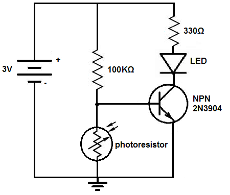
So, for this circuit, 3 volts is powering the circuit. This 3 volts is in parallel to a 100KΩ resistor and the photoresistor. In the middle of these 2 components is connected the base of the NPN 2N3904 transistor.
This is how the circuit works:
When exposed to bright light, the photoresistor's resistance is very low. It drops to around 20-30KΩ. Current travels through the 100KΩ resistor and then has 2 paths- it can either go through the base of the transistor or go through the photoresistor. The base of the resistor to the collector has a resistance of around 400KΩ. Current always takes the path of least resistance. When the photoresistor is exposed to bright light, its resistance is about 20-30KΩ, which is significantly less than the 400KΩ of resistance the base of the transistor has. Therefore, most of the current will go through the photoresistor and very little will go to the base of the transistor. So the base of the transistor is bypassed. Thus, the transistor does not receive enough current to turn on and power on the LED. Thus, the LED is off when there is a lot of light in the surroundings.
However, when it begins to get dark, the photoresistor's resistance becomes very high. Its resistance goes up to over 2MΩ of resistance. This creates a very high-resistance path. Being that 2MΩ is significantly greater than the 400KΩ of resistance that the base of the transistor offers, most of the current will go through the base of the transistor. This means that current does not go through the photoresistor when it is dark, due to this high resistance. Instead current goes through the 100KΩ resistor and through the base of the transistor. The transistor receives enough current to power on and turn on the LED connected to the collector terminal.
So this is how a dark-activated light circuit can work.
Again, as always, variations of this circuit can be done. Instead of using am LED, we can use any other type of lighting
fixture such as a lamp. You may want to use a bright LED. Or you can use
any other various lighting source. You may want to use multiple lights, so you can place different lights in parallel in one another. All that would be needed
is an adjustment in the voltage and current of the circuit. Customize
the circuit according to your needs and preferences.
To see how this circuit functions in real life, see the video below.
Related Resources
How to Build a Dark-activated Switch
How to Build a Hall Effect Sensor Circuit
How to Build a Touch Sensor Circuit
How to Build an Accelerometer Circuit
How to Build a Motion Detector Circuit
How to Build a Motion Detector Alarm Circuit