
How to Build a Laser Diode Circuit
In this project, we will show how to connect up and build a laser diode circuit.
A laser diode is a diode which outputs a laser beam.
Unlike LED light, a laser's light output is more concentrated, meaning it has a smaller and more narrow viewing angle. This means it must be directed at its source more directly in order to be picked up. Laser light is also monochromatic, meaning laser light isn't composed of several lights combined together, but one light of the same wavelength and energy. Normally with LEDs, the different light outputs are based upon different colors combined. One such example is green light. To output green light, blue and yellow lights are combined to give green. Lasers, for the most part, do not follow this. Laser lights have a single spectral color and is almost the purest monochromatic light available.
Laser diodes are used in CD players, CD-ROM drives, and other optical storage drives. They are used in laser printers, laser fax machines, laser pointers, measurement equipment, bar-code and UPC scanners, and in high-performance imagers, as well as various other applications. These are just the most popular and used aspects of them.
To build a laser diode circuit, we must create a driver circuit for the laser diode.
A driver circuit is a circuit which can limit appropriately the amount of current being fed into the laser diode, so that it can function correctly. Too much current and the laser diode will blow. Too little current and the laser diode will not have sufficient power to turn on and operate. Therefore, a driver circuit is needed to give precisely the correct range of current needed so that our diode will operate.
To build the driver circuit, we are going to need a voltage source, a voltage regulator, a diode, an electrolytic capacitor, and a few resistors.
All these parts will be explained below:
Components Needed for Laser Diode Circuit
- Laser diode
- LM317 Voltage Regulator IC
- 1µF electrolytic capacitor
- 0.1µF ceramic capacitor
- 240Ω Resistor
- 300Ω Resistor
- Heatsink
- 4 AA batteries or DC power supply
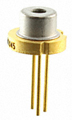
The laser diode we will use in this case is a 650Nm red laser diode made by US-Lasers Inc.
The type of regulator we will use is the LM317 adjustable voltage regulator. The reason we need a heat sink is to dissipate excess heat created by the regulator. For example, if we input 6V into the regulator and it only regulators out 3V, this means that 6V-3V= 3V is dissipated as heat energy. To safely get rid of this excess heat energy, we connect the voltage regulator to a heat sink so that the excess heat dissipates into the air rather than damage sensitive electronic components.
For our input DC voltage, we can use anywhere from 5V-6V as our DC input. With a heatsink, even more voltage can be used
such as up to 9V, since the heatsink will ensure that the difference in input and output voltage will be safely dissipated away as heat.
For this DC input, we can either use a DC power supply and set it to output 5V or we can use 4 'AA' batteries for 6V input or
a 9V battery if used with a heatsink.
Laser Diode Circuit Schematic
The circuit we will build is shown below:
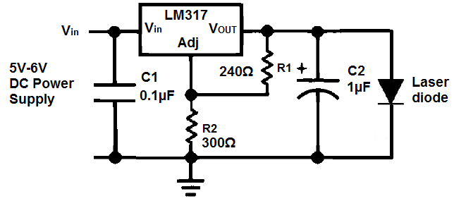
The circuit is actually pretty simple in nature.
The first capacitor, the 0.1µF ceramic capacitor, serves to filter out high-frequency noise from the DC power supply. The second capacitor, the 1µF electrolytic, serves as a power load balancer to smooth out fluctuating signals. The 2 resistors R1 and R2 serve to determine the output voltage of the LM317 regulator. Usually R1 is a fixed 240Ω resistor, as specified by the manufacturer. R2, on the other hand, is decided by the design engineer, based on the amount of voltage he wants the regulator to output. In this case, with the laser diode we have selected, it has an operating voltage of about 2.7V. Therefore, we want the LM317 to output around 2.7V or a little higher. Therefore, we must choose the R2 resistor value so that it outputs this desired voltage.
Since VOUT= 1.25V(1 + R2/R1) and R1= 240Ω, a 300Ω resistor for R2 will output approximately 2.8V. So a 300Ω resistor will be perfect for our application for demonstration purposes. Later on, you can swap out this resistor for a potentiometer to vary the laser diode voltage to increase the brightness or dim it, as to how desired.
However, if you are using a different laser diode, it may have different voltage and current requirements. To calculatoe the output voltage needed output from the LM317 regulator, see the LM317 Voltage and Resistor Calculator. This calculator can find the R2 resistor value needed for the voltage that is desired to be output.
Just so that you can see the operating requirements of the laser diode, these are snippets of the datasheet. If you
want to see the PDF of the datasheet, click on the datasheet link below.
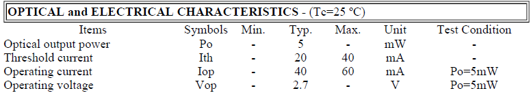
To check the current flowing through the circuit, you an take a multimeter and place it in the DC ammeter setting. Break the circuit opening right at the anode of the laser diode and the anode of the capacitor and measure the amount of current flowing through. At least 20mA is needed for the laser diode to turn on. This is called the threshold current; it again represents the minimum amount of current needed for the diode to function. However, more typically, the operating current is used for a decent amount of power output. For this diode, the typical operating current is 40mA. So 40mA should be fed. To increase or decrease resistance, you can change the value of resistance R2. Increasing this resistance value increases current. Conversely, decreasing this value decreases current. The maximum amount of current which the laser diode should receive is specified by its maximum operating current, which in with this diode is 60mA. No more than 60mA should be fed into the diode or the diode may be destroyed. So make sure to always follow the datasheet specifications.
And this is a simple, yet effective, laser diode driver circuit.
Related Resources
How to Build an LED Driver Circuit
How to Build an LED Flasher Circuit
How to Build an IR LED Circuit
How to Build an Infrared Detector Circuit
How to Build a Proximity Detector Circuit
How to Build a UV LED Circuit