How to Build an OR gate from NAND Gates
A NAND gate is a truly versatile logic gate.
It is referred to as the universal logic gate chip. This is because any other logic gate can be made from the right combination of NAND gates. NAND gates can build them all.
Now we will go over how to build an OR gate from NAND gates.
An OR gate is a logic circuit in which one HIGH value at any of the inputs will turn the output HIGH (on). In our circuit, there will be 2 inputs. If either of the 2 inputs are drawn HIGH (turned on), the output, the LED, will turn on.
We're going to use a 4011 NAND gate chip to build this OR gate circuit.
Components We'll Need
- 4011 NAND gate chip
- 330Ω resistor
- LED
- Jumper Wires
The 4011 quad NAND gate chip can be obtained very cheaply from a number of online retailers for just a few cents. One place it can be obtained from is Tayda Electronics at the following link: Tayda Electronics- 4011 Quad 2-Input NAND Gate IC. However, it is a very popular chip and many electronics parts suppliers have them.
To find out the pinout and how to connect this chip, see How to Build a NAND
Gate Circuit Using a 4011 Chip.
OR Gate Circuit from NAND Gate Conceptually
A 4011 is a quad NAND gate chip. This means it contains 4 NAND gates inside of it. To build an OR gate from a NAND gate, we need to use 3 of the 4 gates that a 4011 NAND chip offers.
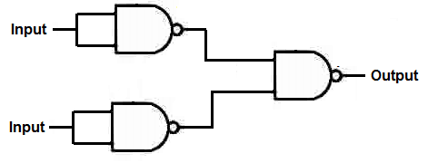
Conceptually, the OR gate is built from NAND gates through the following diagram.
OR Gate Circuit from NAND Gate Circuit
The circuit schematic for an OR gate from a 4011 NAND gate chip is shown below.
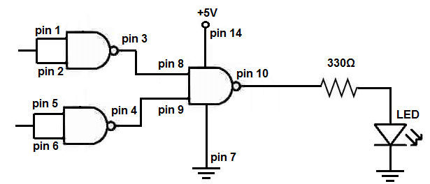
Basically, we tie together the inputs of each of the first 2 NAND gates. This makes the inputs common. We then take one jumper wire from each NAND gate, which will serve as the inputs to our OR gate. The output of these gates feed into a 3rd NAND gate. This forms an OR gate circuit, in which if either of the inputs are drawn HIGH, the output, which in this case is an LED, will turn on.
Below is the breadboard schematic of the circuit above.
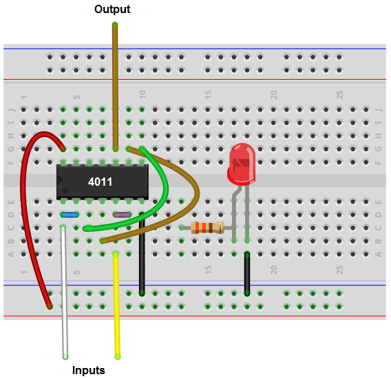
The cyan and white wires represent the inputs to the NAND gate.
The output is connected to an LED along with a 330Ω current-limiting resistor. Following OR gate logic, it will only light up when one or both of the inputs are HIGH (greater than 2.5V).
Related Resources
How to Build a Light Detector Circuit with a NAND Gate Chip
How to Build a Night Light Circuit with a NAND Gate Chip
How to Build a NAND Gate Circuit Using a 4011 Chip