
What is Open Collector Output?
An open collector output refers to an output that is connected to the collector of a transistor.
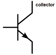
Basically, just think of a transistor. A BJT transistor has a base, a collector, and an emitter.
An open collector output is an output device that is attached to an open collector of a transistor.
By open collector, we mean a collector that is unattached to anything. It's just open.
In order for an open collector output device to work, the open collector has to receive sufficient power.
In order to understand this, you have to understand NPN transistors. In order for an NPN transistor to work, the base and the collector both need sufficient power. The base turns the transistor on. And then a much greater current flows from collector to emitter, but only if the collector has sufficient positive voltage.
A perfect example of an open collector output are voltage comparators. Pretty much all voltage comparator chips, such as the LM311, the LM393, and the LM339 all function as output collector outputs.
Below is shown the internal diagram or makeup of the LM311 voltage comparator chip.
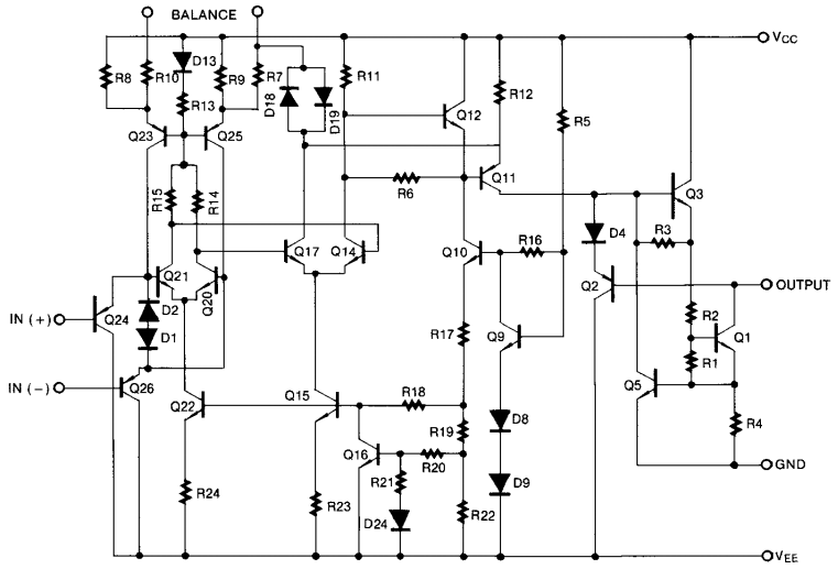
You can see to the right the output pin. You can see that the output stems from the collector of a transistor. And you can also see that the collector isn't attached to anything. It's just open.
In order for a transistor to work, the collector needs to be connected to a positive voltage source and then the load is connnected and then the negative or ground side of the load (if the load has a polarity) is connected to the output pin of the chip.
This is shown in the diagram below.
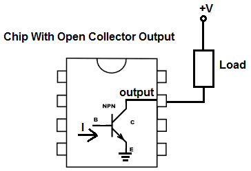
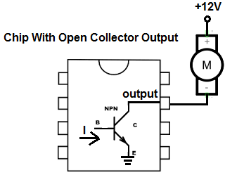
In order for the output device that you connect to the output to work, you must attach the output device to a positive voltage source that is sufficient enough to drive the load. For example, if you connect a 12 DC motor as the output device, the output needs to be connected to +12V and then the load is connected and then the negative and ground side of the load gets connected to the output.
So if you want to connect a load to output on a chip with open collector output, it would have to be configured like above.
So if you wanted to connect a 12V DC motor to an LM311 chip, this would be the schematic diagram
below.
So now you all that open collector output implies.
With open collector output, you simply cannot just connect the output device to the pin and then to ground. Open collector does not work that way. It must have positive voltage and then the load and the negative or ground side of the load connects to the output.
And the same way open collector works is the same way that open drain works. The only difference
is the an open collector uses a bipolar junction transistor (BJT), while an open drain uses a FET transistor.
To see how an open collector circuit is connected, see the building of an LM311 voltage comparator chip. This is a chip with open collector output.
The full documentation of this circuit can be found at
How to Build a Night Light Circuit with an LM311 Voltage Comparator Chip.
Related Resources