
How to Build a Voltage Comparator Circuit Using an LM311
We will go over how to build a voltage comparator circuit the simplest way using the LM311 comparator IC.
The LM311 is a single comparator. This means it is composed internally of one comparator.
It compares these voltage inputs and determines which is the larger value. Based on this, electronic decisions can be made based on which input is greater and which is smaller. Thus, a comparator is very useful in circuits where we measure levels and want our circuit to act a certain way based on whether the level of an input is greater or smaller than a certain threshold.
Before we actually build our comparator circuit, we first must go over in detail the pinout of an LM311 comparator IC, so that you know what each pin is and what each pin does.
An LM311 is a 8-pin chip.
The pinout is shown below:
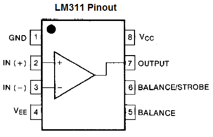
The LM311 has 2 power inputs. These are labeled VCC and VEE. VCC, pin 8, is where the positive terminal of the voltage supply gets inserted into. This supply voltage can be as high as 36V. VEE, pin 4, is the pin we either connect to ground or to negative voltage. In this circuit, we simply connect VEE to ground. These 2 terminals complete the power path for the LM311 chip and gives it the power it needs to function.
The GND pin, pin 1, connects to ground. If you looked at the diagram of the internal components of the LM311, you would see that this pin is the emitter of the output transistor of the chip. So when we connect this pin to ground, we are grounding the emitter of the output. This pin must be grounded in order for the circuit to work properly. If not, the output will always be on, whether the noninverting input is greater than or less than the inverting input.
Next, we have the output pin of the chip. This is pin 7 of the chip. This pin is an open collector pin. It is the collector of the output transistor. So it must be connected to VCC and this is normally done through a pull-up resistor, but it depends on the load we are powering. For an LED, we definitely want a resistor as to limit current to the load.
Next, we have the input pins for the comparator. We now deal with the comparator that is internally within the chip. The comparator has 2 inputs and one output. One input, pin 2, is the noninverting terminal. The second input, pin 3, is the inverting terminal voltage. We will connect a reference voltage to the noninverting terminal. And we will attach a voltage divider circuit to the inverting terminal of the comparator. When the inverting terminal voltage is greater than the noninverting terminal voltage, then output is drawn high to VCC. When the inverting terminal voltage is lower than the noninverting terminal voltage, then the output is drawn low to VEE.
These are the only 5 pins we are going to connect. The other pins which control strobe capability and balance will be left unconnected; we will not use these features.
For our circuit, we will connect a potentiometer to the noninverting terminal. This will allow us to adjust the potentiometer to set a reference voltage level.
We will then connect a voltage divider circuit, consisting of a fixed resistor and a photoresistor, to the inverting terminal of the comparator.
How the circuit works is when the photoresistor is exposed to bright light, it has very low resistance. Thus, very little voltage falls across it (ohm's law tells us this). Therefore, the voltage at the inverting terminal will be less than at the noninverting terminal. So the load connected to the output will be off. However, when the photoresistor is exposed to darkness, its resistance increases dramatically, and so will the voltage that falls across it. Thus, the voltage the inverting terminal will now be greater than at the noninverting terminal, and so the load connected to the output will be turned on.
Thus, our circuit will function as a night light circuit. It will turn on an LED during dark conditions.
Components Needed
- LM311 IC
- Photoresistor
- 33KΩ Resistor
- 220Ω Resistor
- Potentiometer
- LED
- 3 'AA' batteries or DC power supply
The resistors don't have to be exact but should be somewhere in the near proximity of the stated values.
The potentiometer can really be any value.
LM311 Comparator Night Light Circuit
The schematic diagram of the night light circuit is shown below.

So this is as basic of a circuit as you can get with the LM311.
Since this is a night light circuit, we want the LED on when it is dark and off during daylight conditions.
So we use the potentiometer as a calibrator. We tune it so that the LED is off during lit conditions and on during dark conditions. Tune the potentiometer so that this is the case.
This comparator circuit then compares this reference voltage with the voltage produced from the voltage divider between the photoresistor and the 33KΩ resistor. It's a really simple concept. When the photoresistor is exposed to bright light, its resistance falls well below 30KΩ. Therefore, most of the voltage gets allocated to the 33KΩ resistor and little goes across the photoresistor. Thus, the voltage produced by the voltage divider is less than the reference voltage. Therefore, the output is drawn to GND, which means the LED is not powered. However, during darkness, the photoresistor has a very high resistance, so most of the voltage gets allocated across it. Thus, the voltage produced from the divider circuit is above the reference voltage. Thus, the output is drawn high to Vcc, and the LED turns on.
And this is the basis of our voltage comparator circuit.
To see in this circuit in real life, see the video below.
Related Resources
How to Use the LM741 Op Amp as a Comparator
How to Build an LM339 Quad Voltage Comparator Circuit
How to Build a Dark-activated Switch
How to Build a Hall Effect Sensor Circuit
How to Build a Touch Sensor Circuit
How to Build an Accelerometer Circuit
How to Build a Motion Detector Circuit
How to Build a Motion Detector Alarm Circuit