How to Build an LCD Circuit with a PIC18F1220
In this circuit, we will show how to connect a PIC microcontroller chip to an LCD so that text can be displayed on the LCD.
Specifically, we will use the PIC18F1220 chip and the HD44780 Hitachi LCD, which is the most widely used and popular LCD screen in the electronics industry.
This circuit serves as the foundation for connecting microcontroller chips to LCDs. Many, many electronic devices have LCD displays to display data to users of the device. Thus, knowing how to interface a microcontroller to an LCD is an invaluable engineering tool. Through this connection, we can display any possible text to users, including special characters such as the PI symbol, degrees symbol, etc.
With this setup, we display the temperature on an LCD for a temperature circuit. We can display the humidity on an LCD for a humidity sensor circuit. We can display the liquid level of a liquid sensor circuit on an LCD. The examples are endless of the type of data that can be displayed on an LCD that is useful to consumers of a device.
In the circuit, we will show both hardware and software setup so that an LCD can work with a PIC microchip.
Components Needed
- PIC18F1220 Chip
- HD44780 LCD
- 0.1μF ceramic capacitor
The PIC18F1220 is an 18-pin microcontroller. It can be obtained for a few dollars at many online retailers.
The pinout for the PIC18F1220 is shown below.
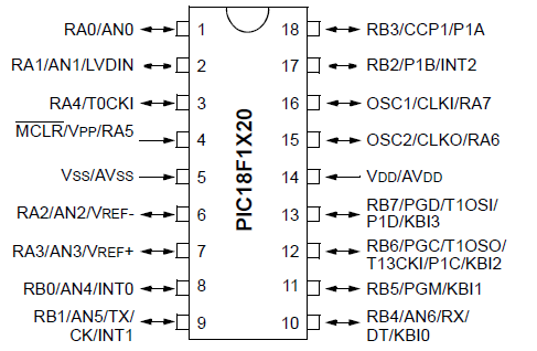
The PIC18F1220 has 16 I/O pins. This means that 16 of the pins can either serve as inputs or outputs. There are 2 major ports, Port A and Port B, which are each comprised of 8 I/O pins. For Port A, these are labeled RA0 to RA7. For Port B, these are labeled RB0 to RB7.
The other 2 pins are the power pins, VDD and VSS. VDD is the pin which receives the positive voltage. VSS is the pin which gets connected to ground. These pins establish power to the PIC chip. Usually a ceramic capacitor is placed on the positive voltage rail to act as a reservoir capacitor.
Apart from the microchip, the other major component is the Hitachi HD44780 LCD. This LCD is the most popularly used one in the electronics industry. And it's relatively inexpensive. You can find different varieties pretty easily for under $10. The type of LCD we will use in this project is the 16x2 LCD, which means it has 2 rows and 16 columns. However, if you have a 20x4 LCD, this can be used too.
If you are unfamiliar with the pinout of the HD44780, please see
HD44780 Pinout, though the pin connections will
be discussed elaborately enough for you to understand how to connect it up.
PIC18F1220 LCD Circuit Schematic
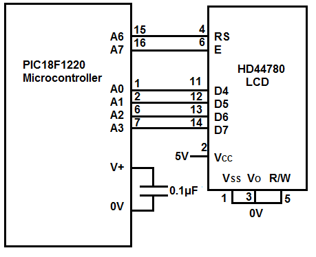
The circuit schematic for the LCD circuit we will build with a PIC18F1220 chip is shown below.
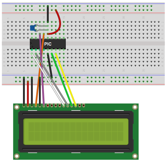
The breadboard schematic of the above circuit is shown below.
We establish power to the chip by connecting pin 14 to 5V through a capacitor that connects on the other end to ground. We connect pin 5 to ground. We establish power to the LCD by connecting pin 2 to the 5V positive voltage rail and pin 1 to ground.
The LCD can be run in one of 2 modes, either in 4-bit operation or 8-bit operation. In this circuit, we will use 4-bit operation because during 4 bit operations we save the need for 4 extra pins. 4 bit operation only utilizes 4 pins on the PIC18F1220 chip. 8 bit operation would need to use 8 pins on the PIC18F1220. All of this requires many more connections, which complicates the circuit. 8 bit operation is a little bit more efficient in operation, but the extra connections really are not worth. Therefore, we utilize the LCD for 4-bit operation. 4 bit operation uses the LCD pins D4, D5, D6 and D7, which are pins 11, 12, 13, and 14, respectively. D4 connects to A0 on the microcontroller chip. D5 connects to A1. D6 connects to A2. And D7 connects to A3.
The RS pin, which stands for Register Select pin, allows the LCD to be in one of 2 modes. If RS=0, then the LCD is in Command (or Instruction) Mode. If RS=1, then the LCD is in Data (or Character) Mode. To learn more about the RS pin, see HD44780 LCD- Register Select (RS) Pin. The RS pin is pin 4 on the HD44780. This pin connects to A6 on the PIC18F1220.
The clock enable pin (E), which acts to accept clock signals, connects to A7 of the PIC18F1220. To learn more about the clock enable pin, see HD44780 LCD- Clock Enable Pin.
The hardware setup is fairly simple. All we need now is the code.
Code
#include The first block includes all the header files and definitions of pins or functions that the LCD will use.
The next several blocks of code defines functions, including the Delay20TCY() function, the setAddr() function, WriteCmd() function,
WriteChar() function, and the WriteString() function.
The last block of code, the main loop, is where we run the functions. In our program, we display several characters as well as blink and move the cursors. We also write a string,
and at the end, we display special characters.
And this demonstrates how to connect and display data on a LCD with a PIC chip.
Related Resources
How to Program a PIC Microcontroller
#pragma config WDT=OFF, OSC=INTIO2,PWRT=ON, LVP=OFF, MCLRE=OFF
#include
#define CLEAR_SCREEN 0b00000001
#define FOUR_BIT 0b00101100
#define LINES_5x7 0b00111000
#define CURSOR_BLINK 0b00001111
#define CURSOR_RIGHT 0b00000110
#define DATA_PORT PORTA
#define RS_PIN PORTAbits.RA6
#define E_PIN PORTAbits.RA7
void Delay20TCY() //20 clock cycles, 2.5ms
{
Delay10TCYx(2);
}
void SetAddr(unsigned char DDaddr)
{
DATA_PORT &= 0xf0;
DATA_PORT |= (((DDaddr | 0b10000000 >> 4)) & 0x0f);
RS_PIN=0;
Delay20TCY();
E_PIN=1;
Delay20TCY();
E_PIN=0;
DATA_PORT &= 0xf0;
DATA_PORT |= (DDaddr&0x0f);
Delay20TCY();
E_PIN=1;
Delay20TCY();
E_PIN=0;
}
void WriteCmd(unsigned char cmd)
{
DATA_PORT &= 0xf0;
DATA_PORT |= (cmd>>4)&0x0f;
RS_PIN=0;
Delay20TCY();
E_PIN=1;
Delay20TCY();
E_PIN=0;
//Lower nibble interface
DATA_PORT &= 0xf0;
DATA_PORT |= cmd & 0x0f;
Delay20TCY();
E_PIN=1;
Delay20TCY();
E_PIN=0;
}
void WriteChar(char data)
{
DATA_PORT &= 0xf0;
DATA_PORT |= ((data>>4)&0x0f);
RS_PIN=1;
Delay20TCY();
E_PIN=1;
Delay20TCY();
E_PIN=0;
DATA_PORT &= 0xf0;
DATA_PORT |= (data&0xf0);
Delay20TCY();
E_PIN=1;
Delay20TCY();
E_PIN=0;
}
void WriteString(const char *buffer)
{
while(*buffer)
{
Delay20TCY();
WriteChar(*buffer);
buffer++;
}
return;
}
void main(void)
{
ADCON1= 0x7F;
TRISA= 0b00100000;
PORTA= 0b00000000;
TRISB= 0b01000000;
PORTB= 0b00000000;
WriteCmd(0x02);
WriteCmd(FOUR_BIT & LINES_5x7);
WriteCmd(CURSOR_BLINK);
WriteCmd(CURSOR_RIGHT);
WriteChar('&');
SetAddr(0x88);
WriteChar('d');
SetAddr(0xC0);
WriteString("Hello");
WriteChar(' ');
WriteChar('x');
WriteChar('y');
WriteChar('z');
WriteChar(' ');
WriteChar(0xEA);
WriteChar(0xED);
WriteChar(0xDE);
while(1);//stop
}