
How to Build a Peak Detector Circuit
In this project, we will show how to build a peak detector circuit using only simple components, a diode and a capacitor.
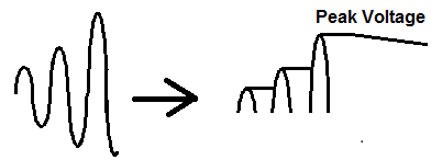
A peak detector circuit is a circuit that is able to measure the peak amplitude that occurs in a waveform. It is able to tell us what's the highest value a waveform reaches.
It is important because it can measure the maximum amplitude value of a signal. It can be used in many applications for any signal that needs to be analyzed for highest maximum value. One application that is used in frequently is sound measuring applications. This is because sound signals vary depending on the level of the sound. For example, it may need to be known what the maximum sound that is generated in a certain place is. The peak detector would be able to measure this maximum sound and output it to us. Therefore, you could know how loud a certain place is. This could be used, for example, at a sports arena, where they want to know how loud the crowd in the arena is. Or it could be used for voice applications to determine how loud a person is, etc. And you could use that data for anything. So the applications for a peak detector circuit is really endless and it's a very useful circuit for many reasons.
It turns out that the simplest peak detector circuit can be built without the need for any complex components such as chips; it can be built simply with a diode and a capacitor.
A diode and capacitor are placed in series with one another. Being that a diode is a one-way current device that only allows current to flow in one direction, we exploit this principle in our peak detector circuit. We place a positive voltage source in series with a forward biased diode and in series with a capacitor. This allows current to flow from the power source through the diode and then to charge up the capacitor. With each new peak in the waveform, the capacitor charges up to that level. It follows the signal, so to speak. And once charged to that peak, it holds it. This is because the charge from the capacitor cannot flow out because the diode prevents it from doing so. To the capacitor, the diode is reverse biased, so no current can flow out from the capacitor. It retains the charge and we are able to read the voltage from this capacitor to tell the peak amplitude of the signal fed into the circuit.
We will explain this circuit in much greater detail below.
We will explain the advantages and disadvantages that come with the circuit, as well as how it can be modified so that the circuit can act according to how we want it to.
However, this circuit still functions as a great peak detector circuit as long as you don't need too much precision, which we'll discuss below.
Components Needed
- Diode
- 100μF electrolytic capacitor
- 10KΩ resistor (optional)
- Transistor (optional)
Any diode really can be used.
All we really need is a device that permits current to flow in one direction but not the other.
However, with the diode you choose, we will need to know the voltage drop across the diode. All diodes have voltage drops across them. This is called the barrier voltage. It is the voltage that is necessary to allow current to conduct across the diode and is necessary to be sustained so that current flow can continue across the diode. So in simple terms, it is the minimum voltage needed across the diode in order for it to conduct current. You can find out this value simply by measuring the voltage across the diode. If you have the datasheet for the specific diode you are using, you can find it out via the datasheet. But we will need to know this because the output at the capacitor, which reflects the peak amplitude of the input signal, isn't directly the voltage read from the capacitor. This is because we must take into account that the diode consumes some of the voltage. Therefore, the voltage at the output, that is from the capacitor, is higher than the input signal by the value by a value that is equal to the voltage drop across the capacitor. So the voltage at the output would be the same as the input if the diode consumed no voltage. But it does. So you must take into account that the diode consumes voltage for operation. Therefore, the voltage at the output is higher by an amount equal to the diode voltage consumption. Being that most diodes consume anywhere from 0.3V-0.7V, the output voltage will be higher by a factor of this amount. So if we have a silicon diode that consumes 0.7V of power and the output signal is 15V, the peak voltage is really 14.3V (15V - 0.7v= 14.3V).
The capacitor should be sufficiently large. For DC voltage that isn't too high, a 100μF capacitor will do well. The more capacitance, the more charge it can hold. So depending on how large the input voltage you are working with determines the amount of capacitance you need. They have a direct relation. So the larger the input volage, the greater the capacitance needed. The smaller the input voltage, the smaller the capacitance needed.
Another factor that we need to be concerned about in terms of the capacitor is the voltage rating. Depending on how large we expect the voltage to scale, we need a capacitor with a
voltage rating matched for that voltage. So we can decide a rough estimate for how high we believe the voltage we reach. Say, we have good estimates the voltage will peak no higher than 30V,
then for that application, a 50V voltage capacitor will suffice. But if the voltage is going to reach, say, 70V, we would make sure the capacitor is rated for a higher voltage than this, say 100V or even
200V. The peak voltage of the input signal should not exceed the voltage rating of the capacitor, because then the capacitor can be damaged, and the circuit will not work. So this is a very important
spec that must be taken into consideration.
Peak Detector Circuit
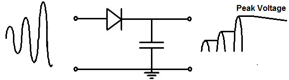
The peak detector circuit we will build with a diode and capacitor is shown below.
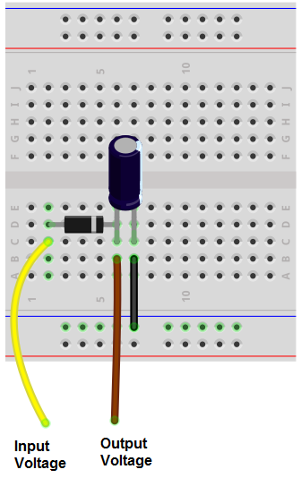
The breadboard circuit of the circuit above is shown below.
So we have a very basic circuit.
We have a diode connected in series to a diode which is in parallel to an open circuit.
The positive power source is connected to the anode (positive terminal) of the diode and the negative power source is connected to ground.
How the circuit works is the power supply allows current to flow through the diode and into the capacitor. The current charges up the capacitor and the capacitor increases in volgtage corresponding to the amount of charge following through it. The capacitor basically follows the input voltage source. It will charge up to the peak voltage of the signal. Once it reaches this voltage, it holds it. This is because if you look at the circuit, the capacitor cannot discharge. It does not discharge back through the diode because the diode is a one-way current device. It only allows current to flow from the anode to the cathode end, but not cathode to anode. The capacitor sees the diode as an open circuit, so no current can flow across. To the right, the capacitor cannot discharge because the circuit is open, so to the capacitor, there is infinite resistance. Therefore, each time the capacitor charges up to meet the peak of the input voltage, it retains that charge until a new peak is reached and it charges up again to match that peak. You can see this in the waveform above.
Also note, as we stated, the voltage across the capacitor isn't directly the peak voltage of the waveform. This is because the diode consumes some voltage. Therefore the voltage measured across the output is actually higher than the input voltage by a factor of the voltage drop across the diode. To get the true peak voltage, we must subtract the voltage that the diode consumes from the output signal. So if we measure the voltage at the capacitor to be 13V and the diode consumes 0.6V, the peak voltage of the input signal is actually 12.4V.
Also note that over time, the capacitor voltage will slowly drift lower over time. This is because there is no such thing as an ideal component. Every component has fallacies. The capacitor will leak small amounts of current over time, slowly decreasing the voltage. The diode allows so small amounts of reverse current. With all these leakage sources, the voltage slowly drifts downward over time. This is why it is best to read the voltage right when it occurs instead of waiting a long time to measure it.
So this is one way to create a peak detector circuit with simple components. The advantage is that it's very simple. The disadvantage is because it's just simple components being used, it leaks current and drifts over time. These inaccuracies don't create a high-precision peak detector. However, it's still great if you just need something basic and not high precision. In other words, it's great for low-precision applications.
To make a distinction, this peak detector circuit functions as a positive peak detector. It detects the peak voltage only on the positive side of the AC signal. All voltage below
0V is clipped because the diode only allows current flow in the forward direction and not the other direction. If you want the circuit to instead detect the negative peak of the circuit,
the diode simple needs to be flipped in the other direction. Then the circuit will detect the peak negative voltage. If you change the circuit to be a negative peak detector and you are using
a polarized capacitor such as an electrolytic capacitor, you will need to switch the capacitor around so that the cathode of the diode connects to the anode of the capacitor.
Circuit Modifications
Now we will talk about modifications we can make to the circuit so that it can act in other ways we may want it to.
So the circuit we created above obtains and holds the charge indefinitely, even though it does decrease slightly over time due to leakage current. However, what if we want to reset the value back to zero, maybe because we want the peak value of a new signal every certain time period. In that case, we want to completely wipe off the charge on the capacitor, so that it discharges completely back to 0V.
One way we can discharge the capacitor is by connecting a resistor in parallel to the capacitor.
This is shown in the circuit below.
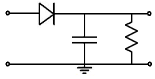
The value of the resistor and capacitor determines how long it takes for the capacitor to charge. The time it will take for the capacitor to completely discharge is 5RC, where R is the resistance and C is the capacitance. So if we have a 100μF capacitor and a 10KΩ resistor, it will discharge in approximately Τ= 5RC=5(10KΩ)(100μF)= 5 seconds. You can adjust this rate to a longer or shorter interval. If you want a longer interval, then you would increase the value of the resistance and/or capacitance. If you want a shorter interval, you would decrease the value of the resistance and/or capacitance.
Let's say that you don't want the circuit to reset every 5 seconds because it's way too short. You want it to reset every minute. That way, it gives you more time to read the signal. Then you could choose the values of 1000μF and 60KΩ. This makes for a 1-minute, or 60-second, self discharge.
With this type of circuit, you can predict how long the circuit takes to discharge. So the circuit self-discharges so that it can read new peaks every 5RC time period.
This is one way of building a peak detector circuit that discharges itself regularly.
Another way of doing it is to connect a transistor to the circuit instead of a resistor.
Below is the circuit showing the transistor connection to the peak detector circuit.
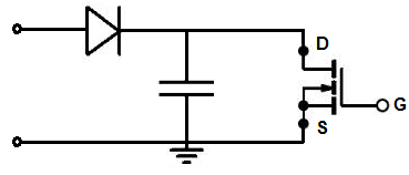
A transistor works really well also.
Again, with this circuit, the voltage across the capacitor is the output voltage minus the diode voltage drop.
It works because when there is no voltage or insufficient voltage across the gate of the transistor, no current flows from drain to source. Therefore, all the voltage is retained across the capacitor, because the transistor acts as an open circuit. However, once we have read the peak voltage and want to reset the voltage back to 0 by draining the capacitor of all its charge, we apply a sufficient voltage to the gate of the transistor. The transistor now conducts current across from drain to source and the capacitor discharges through the transistor.
So this functions like the resistor circuit but it's more advanced and allows for resets whenever we want instead of at a predictable time interval.
We can also connect this circuit to an ADC converter or microcontroller to read the chip. We can program the circuit to
discharge whenever we want by placing a HIGH voltage at the gate terminal.
So these are all peak detector circuits that allow us to measure the peak and allow reset if wanted. Again, it doesn't
provide high precision peak detection but for basic applications where only a good approximation is needed, it works really well.
Related Resources
How to Build a Precision Peak Detector Circuit
How to Build a Peak-to-Peak Detector Circuit