
Push-Pull vs Open-Drain Output Configuration in an STM32 Board- Explained

In this article, we explain the difference in the push-pull and the open-drain configuration and when you would use each one.
There are 2 types of configuration modes we can place an output in for a GPIO pin in an STM32 board.
These output configuration modes are either push-pull or open drain.
This is shown below in the GPIO port output type register (GPIOx_OTYPER),
which allows for the selection
of either Output push-pull or Output open-drain.
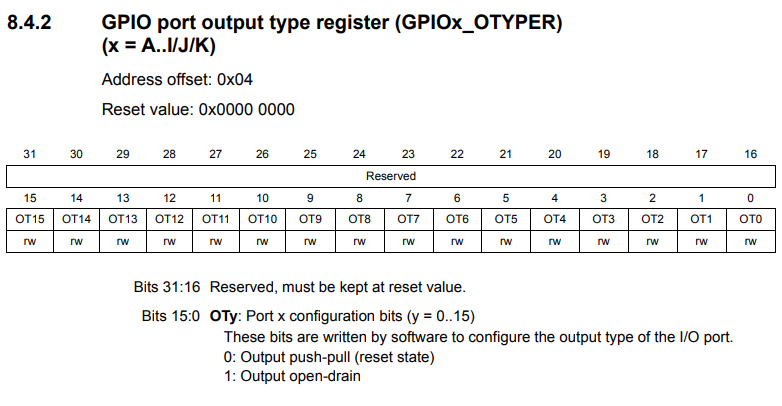
By default, all output GPIO pins are in push-pull state, unless open-drain state is explicitly selected with this register.
Push-pull configuration is the a configuration that most imagine an output to behave in. The configuration has an output value of either ON or OFF, as a digital device behaves. With push-pull state, the output is either ON (a HIGH logic state) or OFF (a LOW logic state).
Using a push-pull configuration is then ideal when you have a device as a load that has 2 states of either ON or OFF, such as LEDs, electric motors, fans, etc.
Open-drain configuration now is entirely different.
Open-drain configuration has 2 states as well, but these 2 states are OFF and Floating (or high-impedance state).
Open-drain isn't ideal for powering ON-OFF devices such as LEDs, motors, etc.
Open-drain has an entirely different use and that use is mostly for serial communication protocols, one being I2C communication.
Being that open-drain produces a floating state, a communication protocol when transmitting data can define this state and make this state from floating (unknown) to either a 1 or 0, based on the data it is transmitting.
Thus, while a push-pull configuration is ideal for powering
ON-OFF loads, an open-drain configuration is suitable for many serial communication
protocols, many of which require open-drain configuration for operation.
To find out more information about how each output configuration
works, see
How Push-Pull Configuration Works and
How Open-Drain Configuration Works. These articles explain more in-depth how each one works from a schematic point
of view.
So this is how push-pull and open-drain configurations differ in their functions and their uses in an
STM32 microcontroller board.
Related Resources