
How to Build a Transient Voltage Suppressor (TVS) Circuit
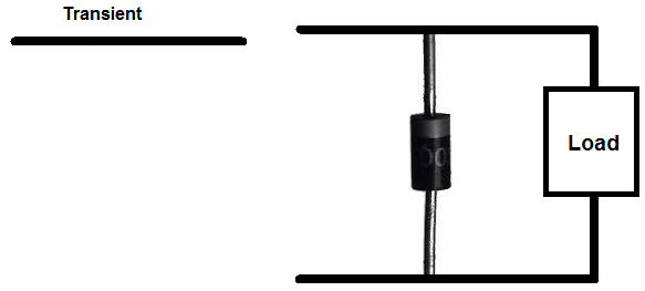
A transient voltage suppressor (TVS) circuit is a circuit which can protect electronic components from transients, which are unintended voltage spikes which can occur in a circuit caused by a variety of factors such as lightning, switch arcing, and motor arcing.
Transients can be very harmful and dangerous for a circuit because it can zap out sensitive electronic components. Many types of electronic components will completely be destroyed if exposed to voltage spikes such as MOSFET chips, because they are very sensitive to them.
Therefore, we must suppress transient voltages and shunt them to ground and away from the electronics. And we do this by creating a transient voltage suppressor circuit. This TVS circuit will suppress transients whenever they occur in a circuit and then shunt the excess power to ground, so that the sensitive electronic components in the circuit do not get damaged or destroyed by them.
And building a TVS circuit is simple. Only a few electronic components are needed to do so.
To build a TVS circuit, we just place the transient voltage suppressor in parallel to the load or circuit that we want to protect. Whenever the input voltage reaches a certain threshold, the TVS suppressor will come into effect and shunt the excess power above this threshold point to ground and away from all components.
Different TVS circuits are needed for DC-powered and AC-powered circuits. Since DC operates and conducts in only one way and doesn't switch polarity, while AC does, both types of circuits need different setups in order to be effective to shunt transients to ground.
In this project, we will build TVS for both DC and AC circuits.
DC Transient Voltage Suppressor Circuit
We will first go over how to build a TVS for circuits with input DC voltage.
To build a TVS for DC circuits, all we need is a diode. One of the best types to use is a zener diode to act as the transient voltage suppressor. You can also choose regular (non-zener) types, but zener works really well because it has such established breakdown voltage points. For the diode which you choose, choose the voltage rating where you want the diode to take effect. For regular diodes, this is the (reverse) breakdown or avalanche voltage, which you can find on its datasheet. For a zener diode, this is called the zener voltage.
So, for example, if you choose a diode with a breakdown voltage of 12V, then it will start shunting all power above 12V to ground.
If you choose 20V, then it will only take effect and shunt transients above 20V to ground and not to components. The rating you choose depends on the amount
of power the circuit
normally operates at and what voltages would be harmful if it were received by the components. If a circuit normally operates at 3V and 5V would damage it,
then you would choose a diode with a breakdown voltage rating of 5V. This way, all voltages above 5V will be shunted to ground and not given to the load in parallel.
Components Needed for DC TVS
- Zener diode or 1N4004 Diode
- Load
- DC voltage
All we need is DC voltage to power the load and a diode, either regular or zener, to clamp all excess voltage to ground above its
rated breakdown voltage value.
DC Transient Voltage Suppressor Circuit
The TVS circuit we will build for DC power is shown below:
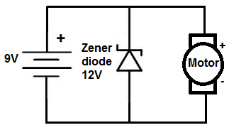
Here, in this circuit, a 9V DC source is feeding the load, which is a DC motor. The zener diode used is rated for 12V. This means that if the circuit were to receive voltage above 12V, the zener diode would then break down and begin conducting reverse current across its terminals, shunting the excess, unwanted power to ground. Below 12V, the diode simply drops the voltage across its terminals. Since voltage in parallel is equal, the load, in this case, which is a motor will receive this voltage. Above 12V, the diode will no longer hold this voltage, since it now conducts current. Therefore, the motor won't receive this damaging excess voltage over 12V.
Placing a diode in reverse bias in parallel to the load eliminates voltage spikes by going into conduction before a large voltage can form across the motor.
And this is how a DC transient voltage suppressor circuit works to eliminate harmful voltage spikes.
AC Transient Voltage Suppressor Circuit
Now we will go over how to build a TVS for circuits with input AC voltage.
To build a TVS for AC circuits, all we need are a capacitor and a resistor in series to form an RC network.
Unlike DC TVS, however, you cannot use a diode to to eliminate voltage spikes. With AC power, the diode will conduct on alternate half-cycles. Using 2 diodes in reverse parallel will also not work because the current will not make it to the load of the circuit. The current will just go through the diodes, essentially bypassing the load. Instead, to create a working transient voltage suppressor with an AC circuit, we use an RC series newtwork placed in parallel with the load. The capacitor absorbs excessive charge and the resistor helps to control the discharge.
For small loads driven from the power line, a resistor value of 100Ω and a capacitor of 0.05µF works for most cases.
Components Needed for AC TVS
- AC Voltage Source
- 0.05µF capacitor
- 100Ω Resistor
- Load such as AC motor
The AC voltage source will likely come from a plug plugged into a US wall outlet.
Warning: Be very careful with AC power coming directly from a wall outlet because it is lethal enough to cause shock. Please
consult a professional before taking power directly from a plug in a wall outlet.
AC Transient Voltage Suppressor Circuit
The AC TVS circuit we will build is shown below:
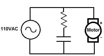
Here, an AC voltage feeds the DC motor. The RC network composed of a resistor and capacitor in series is the TVS. The capacitor absorbs the excess voltage
and discharges it at a rate determined by the resistor. This way transients can be suppressed with AC power.
Related Resources
How to Connect a Relay to a Circuit
How to Connect a Single Pole Single Throw (SPST) Relay to a Circuit
How to Connect a Single Pole Double Throw (SPDT) Relay to a Circuit
How to Connect a Double Pole Double Throw (DPDT) Relay to a Circuit
How to Build an LED Driver Circuit