
How to Build a Current Sensor Circuit

In this circuit, we will build a current sensor circuit.
A current sensor circuit is a circuit that can measure the current flowing through it.
Current sensor circuits are used extensively in systems such as battery management systems in order to detect the current to monitor for overcurrent, a short circuit, and the state of charge of the battery system. This keeps the system safe and can protect the system from devastating, dangerous conditions such as fires.
There's really 2 main approaches to building current sensor circuits for systems such as BMS.
The first approach is using a current sensor resistor, which is also called a shunt resistor or resistive shunt. This is a resistor of a small value (a few milliohms), highly precise, and of high power rating. Current sense resistors are used extensively in low power system that utilize less than 100A. It is low cost and relatively simple to implement.
The second approach is using a hall effect sensor. This is used more for high power systems, which utilize more than 100A such as electric vehicles. The hall effect sensor is more costly and complex to implement. An advantage to using the hall effect sensor method is its ability to work with higher current and it provides electrical isolation if a particular device has multiple sources of power.
In this article, we will focus on building a current sensor circuit using a current sense resistor.
So current sense resistors are widely available online and most cost less than $2, with the majority being under $1.
When you are designing a current sensor circuit that will be based off of a current sense resistor, there are a number of parameters that need to be considered.
It's best to examine the datasheet and specs of the current sense resistor before purchasing to make sure that it suits all your needs.
The first thing you know is what the maximum current that your system can reach. You have to know maximum current conditions because you have to make sure that the current sense resistor doesn't exceed a certain power threshold. Just like regular resistors, current sense resistors have power ratings that should never be exceeded.
So doing the math, power= I2R.
So if you know the maximum current conditions and you multiply it by the value of the current sense resistor you are purchasing, the values should not exceed the power rating of that resistor. Or, in other words, the value of the power rating of the current sense resistor should be higher than the power you calculated for maximum current conditions.
Another thing that is important is the tolerance of the resistor. Most current sense resistors have with a tolerance of ±1%. Highly specialized ones may come with an even lower tolerance. Depending on how precise you need your current sensing to be may alter your pick here but for most basic applications ±1% should suffice well.
The best current sense resistors will have a low value resistance value, a high power rating, and a low tolerance level. The lower the resistance value, the better, because the less power it uses, compared to a higher value resistor, which translates to less power loss.
For this circuit, we will select the Vishay WSLP59312L000FEA current sense resistor.
This is a 2 mOhm, 8W, 1% tolerance current sense resistor.
Let's say we are working with a battery management system that is designed for a maximum of 62.5A.
Doing the math, Power= I2R= 7.8125W
So this is good, because our current sense resistor has a 8W power rating, so this will suffice for our application. Again, make sure you know maximum current conditions and do the necessary calculations to ensure power ratings are not succeeded, so that you don't create a dangerous circuit.
So how a current sensor works is that it's put in series with the circuit.
You have your battery and then you can have the load and current sensor in series such as
shown in the diagram below.
`
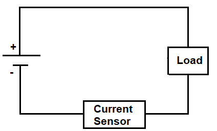
So current is the same in series. So being that we have the current sense resistor connected in series to the battery management system, we know that is the same current that is output by the BMS. So from this configuration, we can always know what current the BMS is outputting.
An important thing to note is that the output from the current sensor circuit must be connected to a chip in order to read the voltage to be able to determine the current. A chip cannot directly measure current. Instead, it measure the voltage drop across the current sense resistor and using ohm's law can compute the current, according to the formula, I= V/R. However, it must be noted as well that the voltage drop across the current sensor is going to be very low, because the resistance value is very low. So the voltage has to be amplified first before it gets read by a chip.
If you have a specialty microcontroller chip, it may be able to do the amplification for you. In that case, you would simply have to create the current sensor circuit and connect its output to the chip without any external amplification circuit, being that the chip has internal circuitry that can amplify it. If not, you have to create your own external circuit to do the amplification.
We examine both approaches below.
Direct To Microcontroller
So if your circuit doesn't need any external amplification and you can connect it directly
to a microcontroller that will amplify the voltage across the current sense resistor, then the circuit
shown below can be built.

Other than the current sense resistor found at the bottom, the other resistors and the capacitors are for filtering.
The µ+ and µ- connections are to connect to the microcontroller which will then read the voltage from the current sensor circuit.
Again, no amplification is done in this circuit. This is only if you are connecting to a
chip that provides amplification in its internal circuitry.
External Amplification Circuit
Now in this circuit, you as the circuit builder provide the amplification from the output of the voltage drop across the current sense resistor.
This amplification can be achieved through the use of a precise op amp.
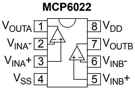
A good op amp chip that can be used is the MCP6022, which is a general purpose operational amplifier. It provides dual op amp use, but for this circuit, only one op amp is needed.
The datasheet for the MCP6022 operational amplifier is shown at the following link: MCP6022 Operational Amplifier Datasheet.
The pinout for the MCP6022 amplifier is shown below.
The op amp circuit we will build is shown below.
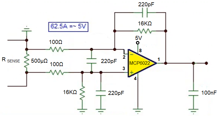
So this circuit is a rugged and proven circuit for current sense resistor circuits.
Notice that the input resistor is 100Ω and the output resistor is 16KΩ; this gives us a gain of 161.
The capacitors are for 220pF capacitors are for filtering.
The 100nF capacitor at the output is also for filtering.
So now you connect the output of this op amp, which is pin 1 to the input of the IC that will read this voltage and controls the battery management system.
If you desire a more in-depth explanation of this circuit, see
Current Sensor Circuit with an External Amplifier.
So these are 2 circuits both utilizing current sense resistors in order to sense current, one
that doesn't provide amplification because it will be connected to a chip that will provide the amplification
of the current sense resistor voltage drop and the other with an external op amp circuitry that provides
amplification which can then be connected to a chip that doesn't need to do any amplification but only
read and manage the system conditions.
Related Resources
How to Build a Current Source Circuit
How to Build a Voltage Sensor Circuit