
What is a Coupling Capacitor?
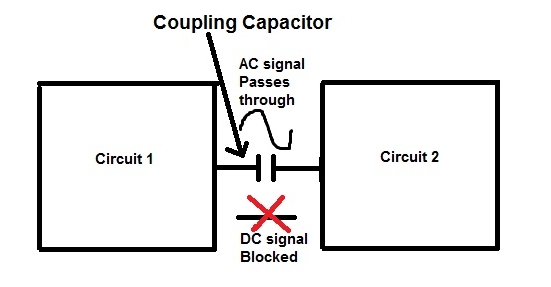
A coupling capacitor is a capacitor which is used to couple or link together only the AC signal from one circuit element to another. The capacitor blocks the DC signal from entering the second element and, thus, only passes the AC signal.
Use of Coupling Capacitors
Coupling capacitors are useful in many types of circuits where AC signals are the desired signals to be output while DC signals are just used for providing power to certain components in the circuit but should not appear in the output.
For example, a coupling capacitor normally is used in an audio circuits, such as a microphone circuit. DC power is used to give power to parts of the circuit, such as the microphone, which needs DC power to operate. So DC signals must be present in the circuit for powering purposes. However, when a user talks into the microphone, the speech is an AC signal, and this AC signal is the only signal in the end we want passed out. When we pass the AC signals from the microphone onto the output device, say, speakers to be played or a computer to be recorded, we don't want to pass the DC signal; remember, the DC signal was only to power parts of the circuit. We don't want it showing up on the output recording. On the output, we only want the AC speech signal. So to make sure only the AC passes while the DC signal is blocked, we place a coupling capacitor in the circuit.
How to Place a Coupling Capacitor in a Circuit
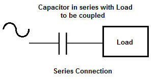
In order to place a capacitor in a circuit for AC coupling, the capacitor is
connected in series with the load to be coupled.
A capacitor is able to block low frequencies, such as DC, and pass high frequencies, such as AC, because it is a reactive device. It responds to different frequencies in different ways. To low frequency signals, it has a very high impedance, or resistance, so low frequency signals are blocked from going through. To high frequency signals, it has a low impedance or resistance, so high frequency signals are passed through easily.
How to Choose the Value of the Coupling Capacitor
Now that we know what a coupling capacitor is and how to place in a circuit for coupling, the next thing is how to choose an appropriate value for the coupling capacitor.
The value of the coupling capacitor depends on the frequency of the AC signal being passed through.
Capacitors are reactive devices, meaning they offer different impedance (or resistance) to signals of different frequencies. To low-frequency signals, such as DC with a frequency of 0Hz, capacitors offer very high resistance. This is how capacitors are able to block DC signals from passing through it. However, as the frequency of the signal increases, the capacitor offers progressively less resistance. The capacitor reactance changes according to the formula, reactance= 1/2πfC, where f is the frequency and C is the capacitance. So you can see that the reactance the capacitor offers is proportional to the frequency and capacitance.
Since capacitors offer less reactance at higher frequencies, a very low capacitance is value is needed to allow them to pass through. So very high-frequency signals need only very small capacitors such as in the picofarad (pF) range.
Capacitors offer greater reactance at lower frequencies. Therefore, they need much larger capacitance values to allow these lower-frequency signals to pass through. So low-frequency signals will require capacitors in the microfarad range.
So coupling capacitors are used in many different applications. One of the most common applications is for amplifiers. However, they can be used in practically any circuit that requires DC blocking with AC coupling, such as radio frequency (RF) applications.
Since audio frequency and radio frequency applications suit a wide range of frequencies that entails frequencies from hertz all the way to megahertz, this covers all the frequencies that are necessary for coupling applications.
Below is a basic rough guideline of capacitors that can be used for various frequencies.
For coupling a 100Hz signal, a 10μF capacitor can be used.
For a 1000Hz signal, a 1μF capacitor can be used.
For a 10KHz signal, a 100nF capacitor can be used.
For a 100KHz signal, 10nF capacitor can be used.
For a 1MHz signal, a 1nF capacitor can be used.
For a 10MHz signal, a 100pF capacitor can be used.
For a 100MHz signal, a 10pF capacitor can be used.
This is a rough estimate that will be effective the majority of the time. The only variable that could affect the above values is the resistance in parallel to the capacitor.
If the resistance in parallel to the capacitor is about 10KΩ or less, all the values will hold true. Usually the resistance is much less than this amount.
However, if the resistance is greater, such as between 10KΩ and 100KΩ, you can divide the above capacitor by 10; meaning you can use even a smaller capacitor. It's perfectly fine if you use the capacitor above, the coupling will work just as well. But you could use even a smaller capacitor, because if the resistance in parallel is larger, that makes the AC signal choose the capacitor path that much easier than the resistor path, because the capacitor path has much less resistance compared to the resistor if the resistor is larger. So as the resistance increases, the capacitance value can decrease. But, again, using a larger capacitor value than what is needed could never hurt. Using a smaller capacitor could.
So this is an effective method for choosing the value of a coupling capacitor. It allows for low-frequency or high-frequency coupling.
While coupling capacitors pass through AC signals to output,
decoupling
capacitors do pretty much the opposite; decoupling capacitors shunt AC signals to ground
and passes through the DC signal in a circuit. Decoupling capacitors are designed to purify
DC signals of AC noise.
Related Resources
What is a Bypass Capacitor?
What is a Smoothing Capacitor?
Capacitor Equations
How to Test a Capacitor