How to Build an AM Radio Circuit with a ZN416E Chip
In this project, we will show how to build an AM radio circuit with a ZN416E chip.
This AM radio circuit can grab AM radio signals from the environment, tune into them, amplify them, so that we can listen to them.
A radio is a device that can detect and grab radio signals from the air, so that we can listen to them.
Many people who do hobby electronics have been drawn to radios. Just like in the past with computers, radios used to be big composed of large tubes. Today, radios can be built with small components and take up very little space.
To this circuit, we connecting a tuning device in order to change the amplitude of the radio signals, so that we can switch to many different AM channels. The tuning device is made up of an inductor and a variable capacitor in parallel to each other. When we change the capacitance of the capacitor, this changes the station, like how you would when you turn the knob of a radio. We can, therefore, listen to many different AM channels.
Even though AM channels seem to offer less than FM, which is what is more popular and listened to, AM is simpler to build. FM, frequency modulation, is more complex; it requires more complex circuitry. It works by changing the frequency of the incoming signal. As we change the frequency of the signal, we can change the FM channel.
But since an AM radio is simpler, we start here. Even though the ZN416E has an internal amplifier inside,
we will connect an external amplifier using an LM386, which is an audio amplifier chip, to boost the signal even more. The output
from this LM386 will then be connected to a speaker, so that we can hear the radio channel we've tuned into.
Components
- ZN416E Radio Chip
- Inductor (ferrite rod)
- 14-365 picofarad variable capacitor
- 2 0.01µF ceramic capacitor
- 2 0.047µF ceramic capacitors
- 0.1µF ceramic capacitor
- 2 10µF electrolytic capacitors
- 100µF electrolytic capacitor
- 10Ω resistor
- 10KΩ potentiometer
- Speaker
The ZN416E chip can be obtained on ebay. It is an older chip, so it's less common to find now; therefore, the price varies. It can still be found on ebay.
It is an 8-pin chip.
The datasheet for this chip can be found at the following link: ZN416E Datasheet.
The pinout of the ZN416E is shown below.
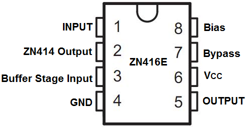
First, to power the ZN416E, we connect 1.5V to VCC, which is pin 6 of the chip. We then connect GND, pin 4, to power ground. This establishes power for the ZN416E. 1.5V is all that is needed to power this chip, so it is very low voltage. A single 'AA' battery can power this chip.
To understand the rest of the pins, it's good to know the internal diagram of the ZN416E chip. Internally, it's composed of a ZN414 chip attached to an amplifier. Various pins on the ZN416E are connected either to the ZN414 chip or the amplifier chip. The pins will be explained below.
The Input pin, pin 1, is the input to the ZN414 chip. This is where we place the tuner circuit to, which is composed of an inductor and variable capacitor. When we adjust this tuning circuit to receive differing AM signals, we feed the AM signal into the ZN414 chip. This then allows it to detect the AM signal we have tuned it to.
The ZN414 output pin, pin 2, and the Buffer Stage Input pin, which is pin 3, connect together so that the output from the ZN414 can flow into the input of the amplifier chip to be amplified. What connects between these 2 stages is a 0.047μF and a 0.1μF capacitor. These capacitors are used for the quality of the AM signal the circuit receives. They are suggested by the manufacturer of the ZN416e to act as a shunt for high-frequency signals to go to ground, preventing them causing noise in certain parts of the circuit.
The Bias pin, which is pin 8, is used simply again for biasing purposes. It connects a 100KΩ and 1KΩ resistors internally and connects the tuning circuit to VCC.
The Bypass pin, pin 7, connects to ground via a 0.01μF capacitor. This provides again a shunt to ground for high-frequency signals to erase noise from the circuit.
The Output pin, pin 5, is where we connect the output of the ZN416E. We are going to connect this chip to an external amplifier (to get even more amplification), so we connect the output to the input of the LM386 amplifier we will use.
A variable capacitor can be obtained on ebay on for a few bucks. This type we will use is between 14 and 365 picofarads, but you can use one up to 500 picofarads.
The inductor or ferrite rod we will use of about of at least 3/8" diameter and 3 1/2" in length. Using longer ferrite roads give higher sensitivity to weak radio signals.
ZN416E AM Radio Circuit
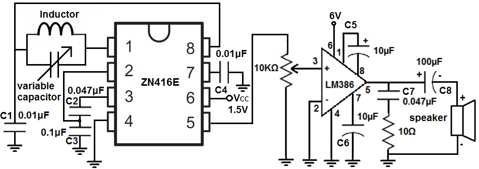
The ZN416E AM radio circuit that we will build is shown below.
We will now explain the hardware connections.
First to connect power to the ZN416E chip, we connect VCC, pin 6, to the 1.5V of power and connect pin 4 to ground. This establishes power to the radio chip.
We also must power the LM386 audio amplifier chip. To see how to connect this chip thoroughly, see How to Connect an LM386 Audio Amplifier Chip. However, seeing this diagram is enough to connect it up. If you want to learn the pin connections in depth, then that link is a good resource. The LM386 needs about 6V of power in order to operate. We connect 6V to pin 6 of the chip and connect GND, pin 4, to power ground. This establishes sufficient power to the LM386 chip.
Back to the ZN416E chip, the we connect our tuning device, the inductor and variable capacitor in parallel, to the Input pin of the ZN416E, which is pin 1. By varying the capacitance of the variable capacitor, we change the AM station. The AM signal that was picked up now gets transferred into the input of the radio chip and then gets amplified, so that we can listen to this station. We place a 0.01µF capacitor, C1, below this tuning device so that it can filter out all nonresonant frequencies that the tuning circuit isn't tuned to.
Pin 2 and Pin 3 of the ZN416E are really for the internal connection between the output from the ZN414 chip and the internal amplifier in the chip. Capacitors have to be placed here for filtering frequencies out. Therefore, we connect 0.047µF and 0.1µF ceramic capacitors here for that reason.
Pin 8 can be seen as like the biasing pin. It connects the tuning circuit to internal resistors on the chip and to VCC.
Pin 7 is the bypass pin. A 0.01µF ceramic capacitor is placed on this pin. It is used to shunt high-frequency signals to ground, decreasing noise in the circuit.
Pin 5 is the output pin. This is the signal output from the ZN416E. Since we want to further amplify this signal with the LM386 audio amplifer chip, we feed this output signal to the input of the LM386, connecting a 10KΩ potentiometer in between.
Now concerning the LM386 connections, we connect the noninverting input to the wiper terminal of
the potentiometer. We connect the inverting terminal to ground. Pins 1 and 8 control the gain of the op amp. Placing a
10µF electrolytic capacitor gives us maximum gain on the LM386. Pin 7 is the bypass pin so we connect a 10µF capactior
to this pin. Pin 5 is the output pin. We connect in parallel to this pin a 0.047µF ceramic capacitor and a 10Ω resistor.
The capacitor acts as a current back for the output. This capacitor drains when current is needed and refills when demand for current is low.
We then connect a 100µF electrolytic capacitor with a speaker in parallel to C7 and the 10Ω resistor.
How the Circuit Works
Now that we went over the connections, we will go over how this circuit works.
Basically, it's very simple. It's just like a radio, as the circuit is.
The tuner to adjust the amplitude of the signal, which represents a radio station, is the inductor in parallel with the variable capacitor. When we adjust the capacitance of the capacitor, it changes the amplitude, or the station. With this, we can tune in to different stations.
What the circuit does is it grabs signals and the signal that matches what the tuner is tuned to gets passed into the circuit and amplified and then eventually played on the speaker. All other signals get shunted to ground through the C1 capacitor.
So once a signal matches the tuned signal, it gets passed into the ZN416 and then passed into the LM386 for amplification. Once it gets amplified by the LM386, it gets played out by the speaker and we can hear what station we're tuned to.
And that's an AM radio with a ZN416E chip in a nutshell.
Related Resources
How to Build a 74HC238 3-to-8 Decoder Circuit with Manual Pushbuttons