
How to Build a Clock Circuit with a 555 Timer
In this circuit, we will show how we can build a clock circuit with a 555 timer.
A clock circuit is a circuit that can produce clock signals. These signals are digital square waveforms, which alternate between on and off.
This is important because many different types of chips need clock signals in order to operate. Many chips such as counter chips, digital potentiometers, and many other types of ICs need clock signals in order to operate. The clock provides a way that a master and slave device can act in synchrony with each other. Either on the falling or rising edge of a clock signal, the 2 devices will work in synchrony so that they can produce a desired outcome.
With a 555 timer, we can produce clock signals of varying frequencies based on the values of the external resistors and capacitor that we choose.
We can produce clock signals of any frequency needed. A 1Hz clock signal will cycle once every second. A 2Hz clock signal will cycle every 0.5 seconds. A 100KHz signal will cycle every 0.00001 seconds or every 10 microseconds. The time period, T= 1/f, where f is the frequency of the signal.
For the 555 timer to work, it must be operated in astable mode. Astable mode is a mode in which there is no one stable state. The circuit switches constantly from low to high, which is representative of a digital square waveform that goes constantly high to low, high to low, high to low, over and over again. So the astable mode switches constantly between HIGH and LOW states. This is in contrast to the other 2 modes, monostable mode and bistable mode. Monostable mode has one state, either HIGH or LOW. Bistable mode has 2 stable states that it can be in. Like astable mode, bistable mode has 2 states but they're stable; in astable mode, they constantly fluctuate back and forth between the 2 states.
A 555 timer is a very versatile. In this circuit, we will build a clock of about 60Hz. This cycles 60 times every
second.
Components Needed
- 555 Timer Chip
- 1MΩ resistor
- 10nF capacitor
- 100nF capacitor
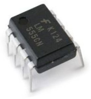
The 555 timer can be obtained very cheaply from pretty much any electronic retailer.
The 555 timer is an 8-pin chip.
If you want to know all the pinout of the 555 timer, what each pin is and what each pin does, see 555 Timer Pinout.
In this circuit, we will connect the 555 timer to be in astable mode.
In this mode, the 555 timer will go from HIGH to LOW, HIGH to LOW, HIGH to LOW, mimicking a digital square waveform, which we will use as a clock.
The connections are shown below.
Clock Circuit Using a 555 Timer
The clock circuit that will produce 60Hz clock signals using a 555 timer is shown below.
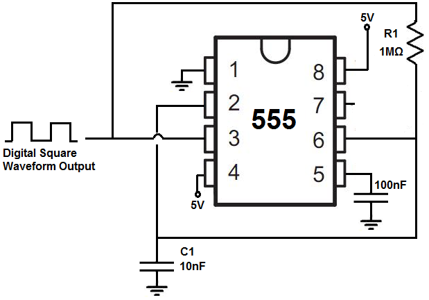
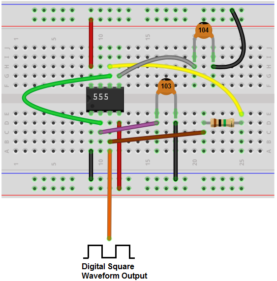
The breadboard schematic of the above circuit is shown below.
This 555 timer is in astable mode.
Astable mode can produce digital square waveforms that go back and forth between HIGH and LOW.
So we have a signal with a frequency of about 60Hz. You must realize with tolerances that resistors have, it may fluctuate a little above or below this level.
And this is how clock pulses can be created with a 555 timer.
If you want to measure the output directly and you have an oscilloscope, all you have to do is connect the positive terminal of the oscilloscope to the output pin 3 of the 555 timer and the negative terminal to ground. Then you should be able to get a picture of the digital square waveforms on the oscilloscope. And then you can see the frequency and time period that a cycle lasts.
So there's multiple ways you can test this circuit.
If you were to change the resistor or capacitor values so that you created a much higher frequency
signal, then it wouldn't make sense to connect it to an output such as an LED because the human eye wouldn't be able to
catch it. It would seem like it's on all the time. If you're dealing with frequencies in the kilohertz range or the megahertz range, then it would not make any
sense. The only thing you can do to measure the circuit would be to connect it to an oscilloscope. And only if you have
an oscilloscope that can measure such high frequencies.
To create a 6Hz signal, R1= 10MΩ and C= 10nF.
To create a 600Hz signal, R1= 100KΩ and C= 10nF.
To create a 134Hz signal, R1= 470KΩ and C= 10nF.
To create a 1.7KHz signal, R1= 33KΩ and C= 10nF.
To create a 43KHz signal, R1= 1KΩ and C= 10nF.
To create a 180KHz signal, R1= 150Ω and C= 10nF.
To create a 252KHz signal, R1= 100Ω and C= 10nF.
To see how to build this same circuit, with the added features of adjustable frequency and adjustable amplitude of the output square wave, see
How to Build an Adjustable Square Wave Generator Circuit with a
555 Timer.
To see how this circuit works in real life, please see the video below.
Related Resources
How to Vary the Brightness of an LED
How to Build an LED Driver Circuit
How to Build an LED Flasher Circuit